

EdwardB’s Mk4 #8674 20th Anniversary Build
*** 5,000 mile report posted 06/19/019. Direct link: https://www.ffcars.com/forums/6064898-post491.html ***
Time to get rolling on another build thread. After a 1,680 mile round trip from Michigan to Wareham, as of August 6, 2015, Mk4 #8674 is now sitting in our garage. This is a 20th Anniversary Edition Mk4, number 03 of 20. This will be my third Roadster build, but a significant first. This is the first build where I am the original owner and taking delivery directly from Factory Five. The first two were purchased from their first owners as partial builds. The Mk3 had a good head start by a pro builder, so a great introduction. The Mk4 was only several months started, so almost like a new build. But time to go it alone from the very beginning. Plus Michigan gave me a really tough time the last go around without my name on the Certificate of Origin. So not going there again.
I thoroughly enjoy driving the completed Roadsters, going to car shows, and cruising whenever I get the chance. Absolutely a blast. The social aspect is great too, with our local club, the extended forum and Factory Five community, etc. But I also really enjoy the whole learning, planning and building process. Each time the builds were completed, I found myself missing the building. With my retirement earlier this year, it didn’t take long to realize another build was something I wanted to do. After some studying (and soul searching) decided it had to be another Roadster, and just to change it up a little spent quite a bit of time planning a 289 FIA build. I was ready to order one during the 50/50 sale several months ago. But then the 20th Anniversary Edition Mk4 was announced, and I was immediately hooked. I called and ordered it while at a rest stop in New York on the way to this year’s Factory Five open house, just minutes after it was made available for purchase. The plan is to sell #7750 when the new build is completed. #7750 is in it's first driving season this year, and now all sorted out and truly a pleasure to own and drive. Frankly, I can’t imagine letting go of it. But that’s the deal, and I’m sticking to it.
So let’s get down to the new non-donor build. The planned use is almost exclusively street cruising. The overall theme is a classic look and feel with completely modern mechanicals and premium driving. Because of the fully optioned anniversary edition, many aspects are already defined. Some of the specifics: Grey powder coat chassis, white powder coat on underhood panels and footboxes (intended to simulate the fiberglass of the originals), balance will be grey powder coat to match the chassis. 2015 Mustang IRS with 3.55 cast iron center section, FFR front spindles, front and rear sway bars, 13 inch front and rear Wilwood manual brakes, Wilwood pedal box with hydraulic clutch, engine driven power steering with 3.0 turn rack, upgraded Koni double-adjustable shocks, 18 inch FF Halibrand style wheels, new Coyote engine with footbox mods to maximize space, Stainless headers, GAS-N side pipes, TKO600 trans with Liberty’s shift mods, leather Roadster seats, Lizard Skin insulation, competition dash (tentatively) with glovebox, Speedhut gauges with GPS speedo, seat heaters, Breeze front battery, dropped floor in trunk, wipers, bumpers and overriders. Undecided about a heater. Haven't done one yet, and haven't missed it. But maybe it's time.
That’s probably enough for now. I’m planning a number of the little mods and touches learned from the first two builds, and maybe some new ones along the way. Notably absent will be a sound system. Spent a lot of time on that with my last build, and find it not very practical. One of my goals is to have a really clean Coyote installation. Not easy with all the wires and hoses. I’ve seen some really great examples. I’ll see how I can do. Color is still undecided. I’m kind of stuck on red, and could easily do that again. But looking at some other options as well. It will have stripes. I’m going to take my time. This isn’t a race. Plus even though I’m retired and have more time than before, I also have other things going on. I’m expecting a roughly two year build, like the first two.
There are 19 items on the backorder list. Many are minor, and won’t hold anything up. A couple others (front spindles, IRS parts) I’ll be watching closely. I’ve completed my inventory. I had a few missing and wrong parts. But not bad and I’m expecting will be quickly addressed. Probably my biggest observation, and I won’t say much at this point, is that I think I might be one of the first people to tackle the new 2015 Mustang IRS. I saw it in person at the Open House, and it’s really impressive and I think will make a great build. But it’s early for FF too. I’ll report more about it in the build thread as progress is made. I do already have the center section, knuckles and hubs on hand and ready to install. Talked about that in this thread: https://www.ffcars.com/forums/17-fa...ums/17-factory-five-roadsters/512881-2015-mustang-irs-components-so-begins.html.
Going through everything, I'm generally pretty pleased. The windshield is now marked as made in Taiwan. The last two were from China. I wonder if they've changed vendors? It seems decent quality with everything nice and tight and clean. The new wheels are noticeably improved over the previous ones. The new tooling and new vendor has produced some nice parts. But those 18 inchers are huge! We'll see how that all turns out. The chassis looks good. The grey powder coating isn't real glossy, but it's nice. It seems they may have done some extra work prepping it before PC. I don't see much weld spatter. At least in many of the obvious places. Having a whole box of white PC'd panels before doing any fitting or drilling is different. I'll need to take care of those. The body looks good. All the panels match up OK at the parting lines. The new front quick jack mount brackets are interesting. I'll still do my usual grommet installation, but now even more to hold things up. I've got the newer style front UCA's. In general, interesting to see how they continue to make interim improvements to the same version. All good I think.
In the true spirit of no pictures it didn't happen, here are a few of pics of the delivery process.
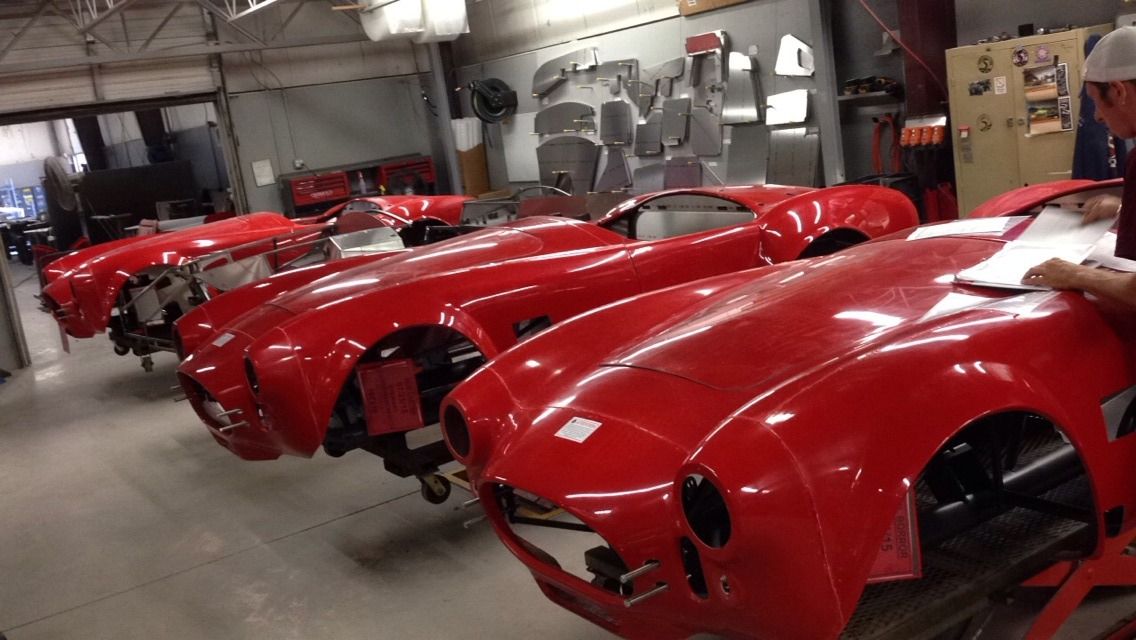
From another forum member who saw my car in final assembly. Mine's on the RH side:
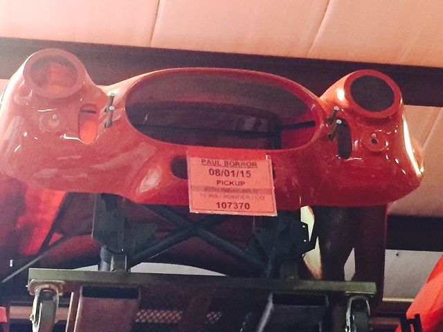
On the rack and ready to go:
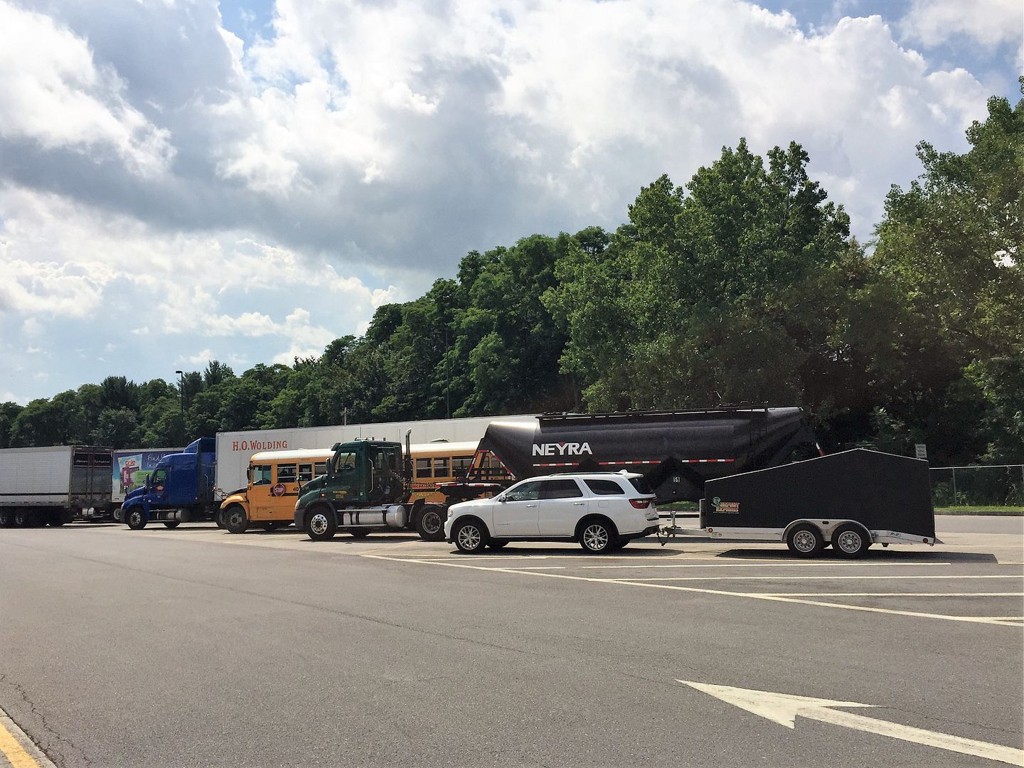
Parking with the big dogs at a rest stop in New York on our way to Factory Five:
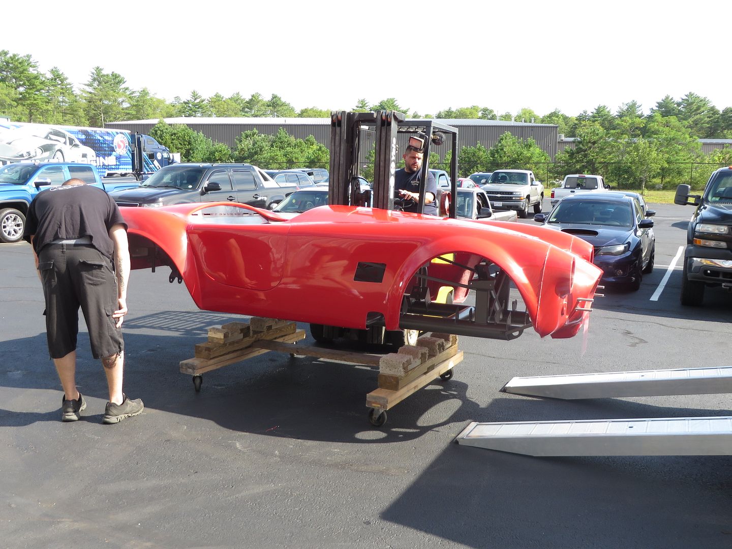
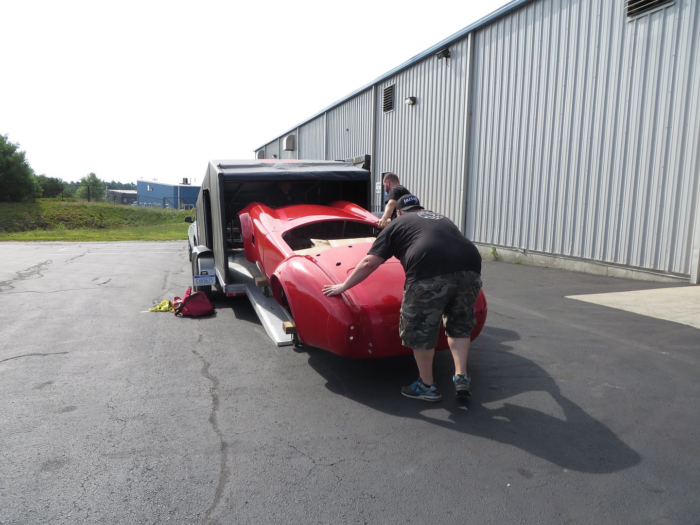
Loading onto the frame cart:
In she goes:
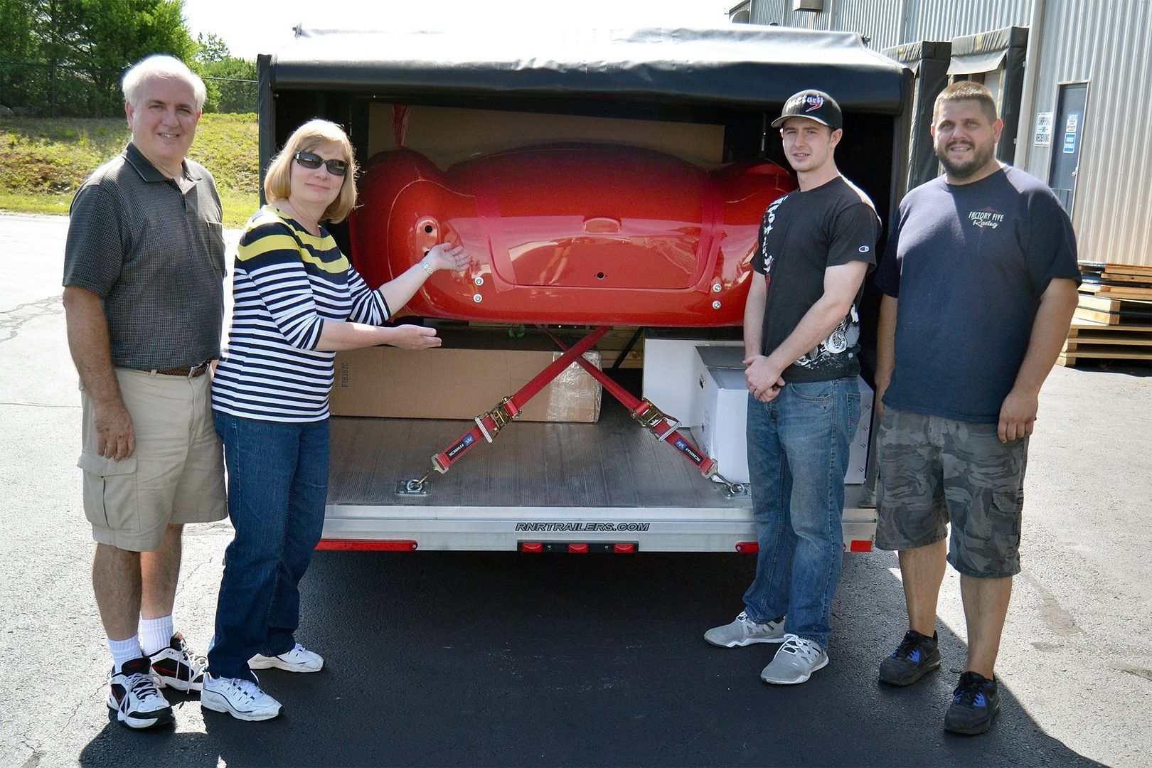
Me looking a little sweaty, while my wife does her best Vanna White impression. Factory Five posted this pic on their Facebook page:
Safely back in Michigan, ready to roll back out:
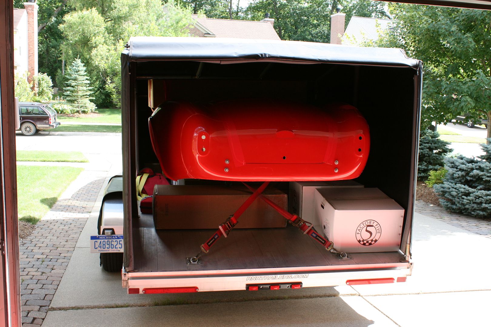
Yes, we used every inch:
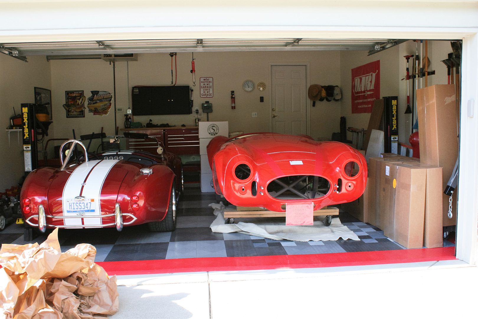
Home in the garage:
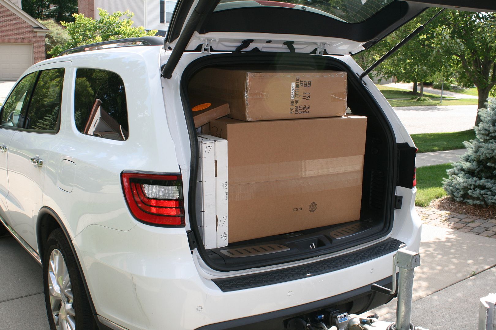
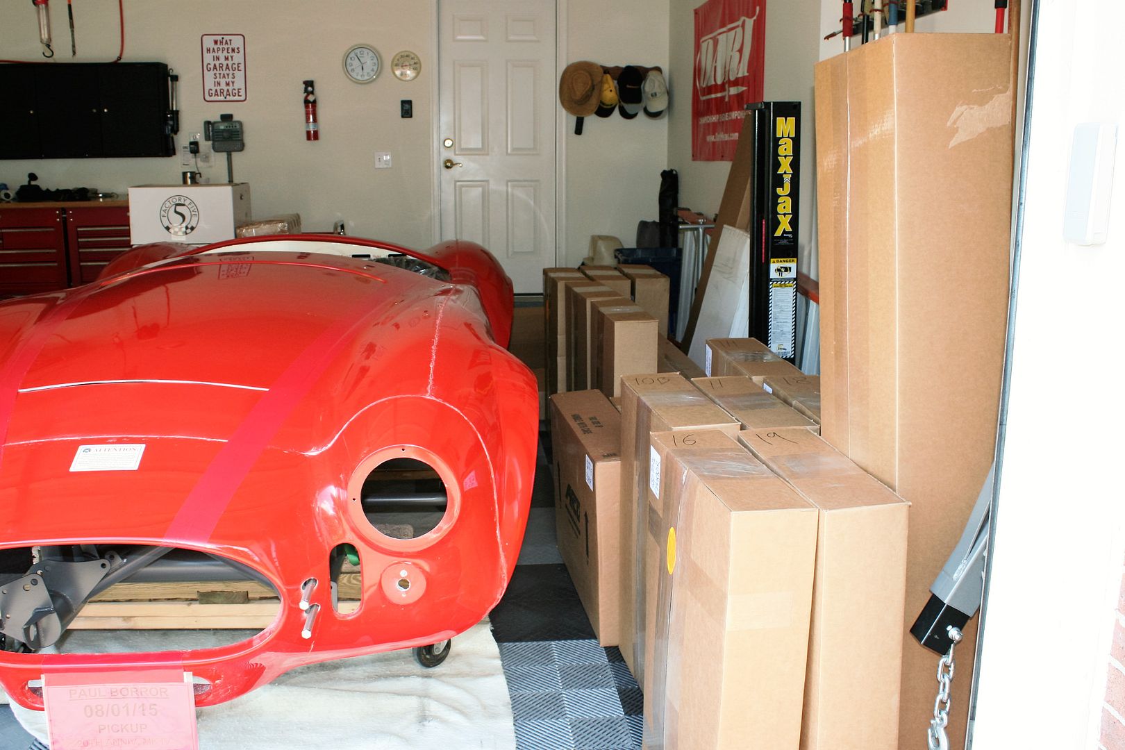
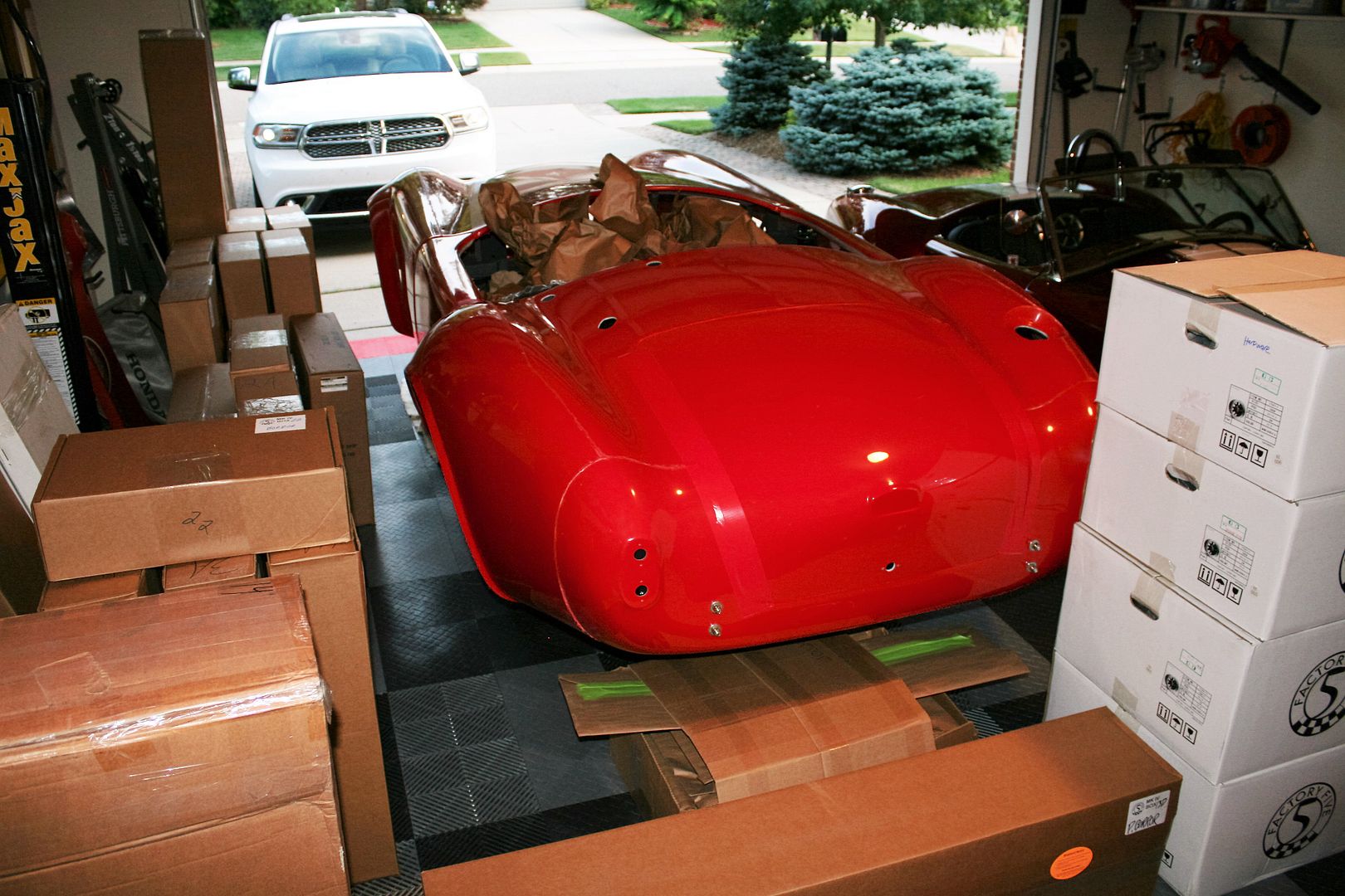
Just a few boxes. All are in the basement now:
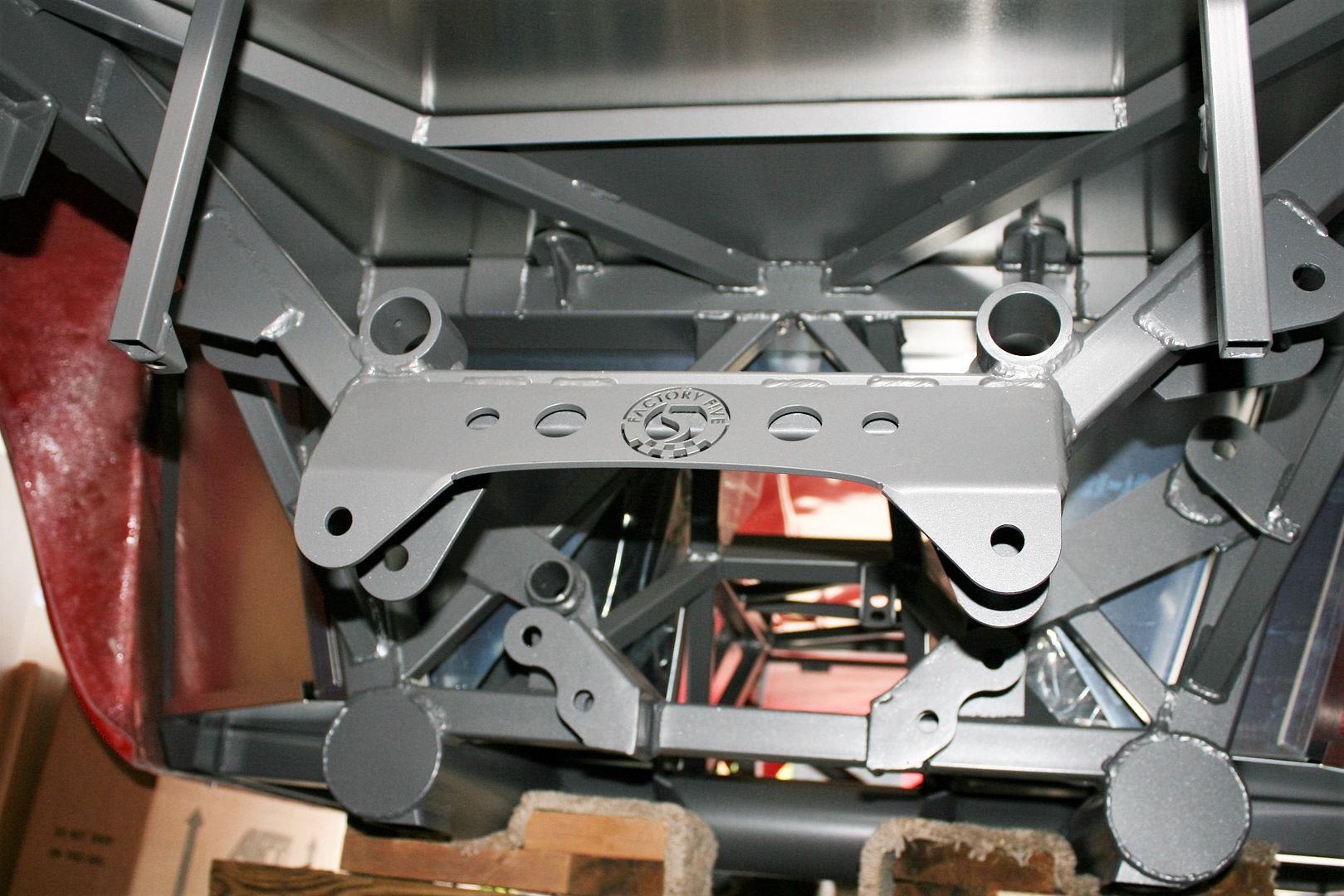
Here's the new IRS chassis setup, before anything installed. I suspect many will be interested to see this:
Here is a slideshow of all the pics taken during the delivery process, if you want to sit through them all: Delivery Slideshow by edwardb123 | Photobucket
I’ll take the body off and start dis-assembly of the rest of the panels next week, in and around Woodward Dream Cruise activities. I’m going to store the body off-site this time around, rather than having it on an elevated buck like my last two builds. I won't miss the head bumping and sore back working under that thing. I’ll get the frame up on the 2-post and start plugging away. Stay tuned for much more!
*** 5,000 mile report posted 06/19/019. Direct link: https://www.ffcars.com/forums/6064898-post491.html ***
Time to get rolling on another build thread. After a 1,680 mile round trip from Michigan to Wareham, as of August 6, 2015, Mk4 #8674 is now sitting in our garage. This is a 20th Anniversary Edition Mk4, number 03 of 20. This will be my third Roadster build, but a significant first. This is the first build where I am the original owner and taking delivery directly from Factory Five. The first two were purchased from their first owners as partial builds. The Mk3 had a good head start by a pro builder, so a great introduction. The Mk4 was only several months started, so almost like a new build. But time to go it alone from the very beginning. Plus Michigan gave me a really tough time the last go around without my name on the Certificate of Origin. So not going there again.
I thoroughly enjoy driving the completed Roadsters, going to car shows, and cruising whenever I get the chance. Absolutely a blast. The social aspect is great too, with our local club, the extended forum and Factory Five community, etc. But I also really enjoy the whole learning, planning and building process. Each time the builds were completed, I found myself missing the building. With my retirement earlier this year, it didn’t take long to realize another build was something I wanted to do. After some studying (and soul searching) decided it had to be another Roadster, and just to change it up a little spent quite a bit of time planning a 289 FIA build. I was ready to order one during the 50/50 sale several months ago. But then the 20th Anniversary Edition Mk4 was announced, and I was immediately hooked. I called and ordered it while at a rest stop in New York on the way to this year’s Factory Five open house, just minutes after it was made available for purchase. The plan is to sell #7750 when the new build is completed. #7750 is in it's first driving season this year, and now all sorted out and truly a pleasure to own and drive. Frankly, I can’t imagine letting go of it. But that’s the deal, and I’m sticking to it.
So let’s get down to the new non-donor build. The planned use is almost exclusively street cruising. The overall theme is a classic look and feel with completely modern mechanicals and premium driving. Because of the fully optioned anniversary edition, many aspects are already defined. Some of the specifics: Grey powder coat chassis, white powder coat on underhood panels and footboxes (intended to simulate the fiberglass of the originals), balance will be grey powder coat to match the chassis. 2015 Mustang IRS with 3.55 cast iron center section, FFR front spindles, front and rear sway bars, 13 inch front and rear Wilwood manual brakes, Wilwood pedal box with hydraulic clutch, engine driven power steering with 3.0 turn rack, upgraded Koni double-adjustable shocks, 18 inch FF Halibrand style wheels, new Coyote engine with footbox mods to maximize space, Stainless headers, GAS-N side pipes, TKO600 trans with Liberty’s shift mods, leather Roadster seats, Lizard Skin insulation, competition dash (tentatively) with glovebox, Speedhut gauges with GPS speedo, seat heaters, Breeze front battery, dropped floor in trunk, wipers, bumpers and overriders. Undecided about a heater. Haven't done one yet, and haven't missed it. But maybe it's time.
That’s probably enough for now. I’m planning a number of the little mods and touches learned from the first two builds, and maybe some new ones along the way. Notably absent will be a sound system. Spent a lot of time on that with my last build, and find it not very practical. One of my goals is to have a really clean Coyote installation. Not easy with all the wires and hoses. I’ve seen some really great examples. I’ll see how I can do. Color is still undecided. I’m kind of stuck on red, and could easily do that again. But looking at some other options as well. It will have stripes. I’m going to take my time. This isn’t a race. Plus even though I’m retired and have more time than before, I also have other things going on. I’m expecting a roughly two year build, like the first two.
There are 19 items on the backorder list. Many are minor, and won’t hold anything up. A couple others (front spindles, IRS parts) I’ll be watching closely. I’ve completed my inventory. I had a few missing and wrong parts. But not bad and I’m expecting will be quickly addressed. Probably my biggest observation, and I won’t say much at this point, is that I think I might be one of the first people to tackle the new 2015 Mustang IRS. I saw it in person at the Open House, and it’s really impressive and I think will make a great build. But it’s early for FF too. I’ll report more about it in the build thread as progress is made. I do already have the center section, knuckles and hubs on hand and ready to install. Talked about that in this thread: https://www.ffcars.com/forums/17-fa...ums/17-factory-five-roadsters/512881-2015-mustang-irs-components-so-begins.html.
Going through everything, I'm generally pretty pleased. The windshield is now marked as made in Taiwan. The last two were from China. I wonder if they've changed vendors? It seems decent quality with everything nice and tight and clean. The new wheels are noticeably improved over the previous ones. The new tooling and new vendor has produced some nice parts. But those 18 inchers are huge! We'll see how that all turns out. The chassis looks good. The grey powder coating isn't real glossy, but it's nice. It seems they may have done some extra work prepping it before PC. I don't see much weld spatter. At least in many of the obvious places. Having a whole box of white PC'd panels before doing any fitting or drilling is different. I'll need to take care of those. The body looks good. All the panels match up OK at the parting lines. The new front quick jack mount brackets are interesting. I'll still do my usual grommet installation, but now even more to hold things up. I've got the newer style front UCA's. In general, interesting to see how they continue to make interim improvements to the same version. All good I think.
In the true spirit of no pictures it didn't happen, here are a few of pics of the delivery process.
From another forum member who saw my car in final assembly. Mine's on the RH side:

On the rack and ready to go:

Parking with the big dogs at a rest stop in New York on our way to Factory Five:

Loading onto the frame cart:

In she goes:

Me looking a little sweaty, while my wife does her best Vanna White impression. Factory Five posted this pic on their Facebook page:

Safely back in Michigan, ready to roll back out:

Yes, we used every inch:

Home in the garage:

Just a few boxes. All are in the basement now:


Here's the new IRS chassis setup, before anything installed. I suspect many will be interested to see this:

Here is a slideshow of all the pics taken during the delivery process, if you want to sit through them all: Delivery Slideshow by edwardb123 | Photobucket
I’ll take the body off and start dis-assembly of the rest of the panels next week, in and around Woodward Dream Cruise activities. I’m going to store the body off-site this time around, rather than having it on an elevated buck like my last two builds. I won't miss the head bumping and sore back working under that thing. I’ll get the frame up on the 2-post and start plugging away. Stay tuned for much more!