Factory Five Racing Forum banner
261 - 280 of 379 Posts
Discussion starter · #262 ·
Here they are on my Gen 2 coupe.

Click below only if you want a spoiler:
https://www.ffcars.com/forums/21-ff...ums/21-ffr-type-65-coupe/515033-matt-s-65-coupe-build-thread-6.html#post5295145

By the way, they work awesome.

-Matt
Thanks for posting the pic. That's better than any others I found. The Gen 3 is different in that area, so the mounting will be different. But otherwise very similar. Design/fabrication underway. I'll post the results in the next couple days.
 
Discussion starter · #263 · (Edited)
Hood Rollers

Well my teaser picture of the inline skate wheels created a few more comments than I was expecting, and their purpose was correctly identified on both forums. Today I have the hood rollers basically completed. Still need the brackets powder coated then will bolt on for good. This is another one of those optional upgrades, but really is a nice addition. It's a bit inconvenient raising and lowering the hood (or cowl in this case I guess) and typically had to go back and forth on each side a couple times to keep it from hitting the corner of the body opening or trying to knock off the lowest bumper on each side. Or ask someone to help and spread as it opened and closed. With the rollers in place, it’s a one-person job from one side and is effortless without hitting anything. I removed the bottom bumper on each side because the rollers provide the same function in that area. Super nice mod that I highly recommend.

As I mentioned previously, a complete version is listed at Whitby’s. But are for the previous Gen Coupes. They mount in an area below the latching U-bolts. The Gen 3 is changed in that area, so can’t mount in the same place or fashion. Could be mounted to the aluminum footbox sides, and probably would be just fine. But I decided to come up with a design more compatible with the Gen 3. Plus, I did it for about one third the cost, if you consider the time spent free of course. Like budget is much of a consideration at this point. :rolleyes:

After even more sitting and staring, decided to mount them to the side of the steel bracket that the U-bolts are attached to. They angle back to the frame and have a relatively large surface to attach to. First made a pattern out of cardboard. Then made some very rough concept pieces out of .040 aluminum. Could have left the bracket square like the cardboard pattern. But decided they needed a little more flair so add the circles where the wheels mount. Ended up looking a little like Micky Mouse ears. After some tweaking and changes, liked what I had and made the final pieces from .125 thick 6061 aluminum. I was going to make them out of mild sheet steel. But decided on the aluminum since it’s so much easier to work with considering the tools I have. I’m very satisfied with the strength. They’re solid and work perfectly.

There’s already a slot in the U-bolt mount, so used that for two mounting bolts. I lengthened it on the outside of the footbox so that one bolt could be on the outside. Both bolts could be inside. But I wanted one closer to the bend and the rollers to provide as much rigidity as possible. For the inside one, had to open the slot slightly for the 5/16-inch carriage bolts I used. A smaller bolt size could work, but I had those on hand so used them. The minor mods to the frame U-bolt mounts was easy on the side with the access cover. Not so easy on the other side where I have all the aluminum finalized. If you’re thinking about this mod and mount them the same way, highly recommend fitting them up before mounting the aluminum panels. Would be much easier. Here are pics.

Developing the concept and rough prototypes.

Image

Driver side final version.

Image

Passenger side final version with access cover off showing carriage bolt attachments, and with cover on.

Image

Image

Cut required in underside of cowl flange to clear roller assembly and U-bolt latches.

Image

Next up I'll finalize the pontoon alignment pins and a little more remaining bodywork. Then on to final electrical and lighting. Completely off topic side note. My first build, a Mk3 Roadster with a warmed up 306 is owned by a good buddy in our local club and see it often. He had a Factory Five premium top put on it (those are really nice) and had a shop install the Saturn Vue electric power steering system. It’s now over 10,000 miles and hadn’t been tuned up since I sold it to him 5 years ago. He’s been doing the usual fluid changes, lube, etc. But hadn’t touched anything else on the engine. He asked if he could bring it over and have me check it out. It was fun getting my hands dirty on my old build. He’s taking great care of it and still looks brand new. Cleaned up the contacts in the MSD distributor and put some new plugs in it. Other than that, everything looked perfect and runs great. Was a good time with both friends. :)
 
Nice work. Those turned out really well. I like the side mount idea. Looks like it belongs there.
 
  • Like
Reactions: edwardb
Discussion starter · #265 · (Edited)
Pontoon Alignment

One of the remaining tasks for my seemingly never-ending body fit-up was to get the cowl and pontoons lined up the way I wanted them. Seems like a pretty simple thing, but was a little more complicated once I dug into it. There were two issues, both that I’ve mentioned before. First, I had an alignment issue between the bottom of the cowl and top of the pontoon on the right side. OK at the back, but to a hard interference fit at the front behind the wheel. No amount of juggling the body or the cowl eliminated the problem without creating other issues. I could pull the pontoon down a little and anchor to the splash guard. But not nearly enough. So I’ve left it to now to resolve. Second, I found that the gas shocks push the cowl out of alignment when it’s closed. Without anything holding it, moves the entire cowl forward 3/16 to 1/4-inch when you close it. Kind of a big deal, and not good if you want everything to line up nicely and position consistently. Some have solved the problem by removing the gas shocks and using a prop rod arrangement instead. That’s a good solution, but I wanted to stay with the gas shocks if possible.

Part of the solution for both issues is alignment pins for the front of the pontoons. The kit provided some receptacle pieces for one side. But the pins provided were much smaller than the 3/8-inch holes in the receptacles. Plus, they were plain pins with no obvious way to mount. Talking to other builders, seems I was probably provided the wrong size pins, as 3/8-inch ones are apparently available. But rather than pursue that, fabricated my own pins and mounts. One of the challenges here is the pins not only need to do the alignment task, but IMO need to be robust enough to catch and hold the cowl against the forward push of the gas struts.

First up though was to fix the alignment issue between the cowl and the pontoon. After a lot of consideration, decided a little glass work was my only option. I cut through the glass at the top corner of the pontoon about 18-inches back from the front corner. Then made another tapered cut starting about 1/4-inch wide at the front down to zero at approximately 18-inches. Then, using the closed cowl and paint stick pieces as spacers, glued the edge back down with HSRF to provide the needed clearance. When that set up, put a healthy filet of HSRF on the inside of the corner where I cut. Then added two layers of 8-ounce glass on the inside with vinyl ester resin. Turned out pretty well with just a little bit of additional HSRF filler. Now I had the clearance and alignment I needed.

Next I made the alignment pins and mounts out of 1/4-inch flat steel stock and cut down 3/8-inch SS bolts. Tapped the hole in the mount for the 3/8 x 16 threaded portion of the pin and used a jam nut on the bottom. Looked like this before installing. The bottom piece is the receptacle provided in the kit. Had to trim one edge slightly to fit where I wanted it. Note this is an early picture. I had to make new longer pins. Slight miscalculation. :(

Image

Won’t go through all the steps, but got the cowl and pontoons positioned where I wanted them and clamped everything down. Then attached the pontoons to the lower splash guards. Then located the holes for the alignment pins and receptacles. I bonded the pieces in with HSRF, and don’t plan to have anything removable except the pin itself. Since there wasn’t a lot of surface area on the receptacles to bond to, I added a couple 8-32 bolts in each.

Left side pin mounted to the steel plate bonded underneath in the front corner of the pontoon.

Image

Mating receptacle mounted on the inside of the cowl. Ditto everything for the right side.

Image

I’m pleasantly surprised how this turned out. Between the gas struts, the rollers shown in the last update, and now the mostly self-guiding alignment pins, the cowl easily drops down into place and latches in exactly the same place every time. The alignment pins easily manage the push from the struts. There will be some minor body work, but generally the gaps and panel alignment turned out really well. Hopefully my body/paint guy will appreciate all the work here! I did have to sand the profile some where the cowl and pontoons meet at the rear of the front wheel wells. With that, the wheel well outlines match reasonably well. That was one of the areas I was focused on. I’ve noticed on some Coupes that area doesn't align very well. Couple of quick side views. You can see the repair I made on the right side.

Image

Image

Now that I have this part done, I can do some final tweaking on the cowl to body gap and that’s it. Only remaining fiberglass work is to get the rear spoiler fitted and I’m going to cut in a third brake light. I’ll be glad to move on from this part of the build.
 
I sure hope FF appreciates and recognizes all of the outstanding assembly techniques you had developed and shared. They need to pay you a royalty for your efforts when they up date their build manual. Maybe you could be a tech support consultant you you get bored building? Right, when do you ever get bored young your creative mind dreaming up different designs and how to's!
Keep it going, and thanks for sharing!
Bob Mac
 
Discussion starter · #267 · (Edited)
Lights and More Lights

Since the last update, finished glass prep work on the spoiler, got it mounted, and have all the lights mostly mounted. Nothing wired yet. I’ll get the weather packs ordered and wrap this up. The lights are the ones I discussed back in post #55. 100% LED’s.

For the spoiler, trimmed it to a 3/4-inch flange all around, had a couple spots on the edge that needed a little repair, then determined the mounting holes. I’m mounting it with eighteen 8-32 SS button heads evenly spaced around. All pretty straightforward. I’ve mentioned before I wanted to add a third brake light to the spoiler. The light I picked (Maxxima M63319R LED) was too thick to just surface mount. Thought that would look a little clunky. But the space inside the spoiler wasn’t enough to completely flush mount. So took my time to lay out a hole in the spoiler that matched and came up with a mounting method that kind of suspends it in the hole. These pictures give an idea.

Image

Image

With that, laid out the lights for the back. The running/stop/turn lights are the ones from the kit and I put them right where the manual says. Same for the license plate light and bracket. I’m installing back up lights, but not completely decided on this yet. I saw an idea in another build thread somewhere about putting the backup lights under the grilles on the back. Interesting idea. But after trimming the grilles to fit, the lights are too thick. So right now, I’m leaning toward the two smaller LED’s taped in place in the picture. Haven’t committed to drilling the holes yet. I have a single square LED backup light that could inset in the bottom center. But not feeling that look. Note the LED running/stop/turn lights from Factory Five are a bit oversize but are very bright. I like them a lot. The third brake light in the spoiler also has a low intensity running light circuit, which I will use. This thing should be very visible from the back. I don’t know about you, but I’ve done several cruises where the car in front of me had lights I could barely see. It’s a bit unnerving and I’m paying close attention. No telling what the average driver may/may not see. Don’t want to be that guy.

Image

For the front, after some additional trimming to the factory cut openings, have the headlight buckets mounted. I’m using 8-32 SS screws and lock nuts versus the supplied self-tapping screws. Personal preference. Note also it’s necessary to locate and drill a hole in the body directly under the headlight trim retaining screws. No way to install those any other way. Mentioned in the manual but would be easy to miss. The running and turn signal lights mounted per the manual. I had to get a little creative to modify the flat mounts on the KC HiLiTES fog lights I'm using to mount centered in the round buckets. Easy fabrication that I won’t try to explain, but no big deal. Just more time.

Image

Image

That’s it for now. Happy Mother’s Day to all the mom’s out there.
 
Discussion starter · #268 · (Edited)
Rear Hatch

While waiting for weather pack connectors to arrive so I can wrap up the exterior lights, decided to tackle the rear glass hatch. The hatch itself is a beautiful piece. I’ve been handling it very carefully. I don’t know how much a replacement would cost, but don’t want to find out. It’s marked as made in the USA, and the DOT code shows it came from Auto Temp, Inc. in Batavia, Ohio. I’m impressed. Additionally, it fits the body opening perfectly. So good job by everyone there. Now to getting it hinged and working.

Some months ago, Factory Five sent a package with several updated aluminum panels, discussed previously. Also in that box were new hatch hinges. Two pieces for each side, and longer than the original ones that come with the kit. No explanation was provided for the new longer pieces. I seem to recall reading in an earlier build thread about the hinges hitting something before the hatch opened all the way. But that’s a vague memory and may not be correct. The manual shows taking a pretty big cut out of the body for the hinges, so also thought maybe that was the reason. But as I found out later still required a small relief cut. Whatever the reason, I'm using them.

The hinges are attached to the roof roll bar along the front of the hatch opening with clamps that have a pivot piece welded to them. I had them powder coated, so had to clean up the powder coat some for them to fit properly. But then fit well and are very robust. I assembled the arms onto the hinge mounts per the instructions, except that I changed out the little plastic bushings with bronze sleeve bushings. They’re the same size as used lots of places on these builds (Roadster doors, trunk, etc.) and I had some around. Call me old school. I just like the bronze bushings better than plastic. Followed the instructions to install the hinge pieces, gas strut attachments, and latch onto the glass hatch. All nice quality parts and fit per the instructions.

The kit comes with a special self-adhesive gasket that goes around the hatch opening to seal and hold the perimeter spacing. Obviously, that can’t be installed until after paint. So stacked some wood spacers and taped them into the four corners of the opening so the glass sat up at the proper height. Then set the hatch in place and installed the hinges. It’s a little fiddly to get the roll bar clamp piece at the right place and the hinge arms aligned. But not bad. That’s when I found out I’d needed to cut the body to clear the hinges. Not nearly as much as shown in the manual though. Looked like this when done.

Image

Next up was the gas struts. Here there was a problem. The manual shows additional roll bar clamps along the hatch sides to attach the gas struts. No parts like that in the kit. Instead there were flat gas strut brackets provided. Just like the ones mounted in the front cowl. Looked through a number of build threads, and eventually found several builds that used these parts. Confirmed they were mounted along the side lip of the body hatch opening. Determined the proper location to mount them where the gas strut wouldn’t be bottomed out and attached. Like I’ve done in other places, mounted them permanently with HSRF on the inside. Just used two bolts since they’re bonded plus the third would be very close to the edge. I’m going to change the bolts pictured here and countersink, bury, and eventually paint over.

Image

Finally, dealt with the latch. The kit provides a somewhat small catch and a spacer. Probably would work OK, but looked a little wimpy to me and I didn’t care for the added spacer. So quickly fabbed a new piece out of 1-inch aluminum 90° angle stock. Looks better (IMO…) and has a larger contact surface on the body. I cut a real short piece of the gasket material and used it to set the location. I can adjust further when put on for good. Also need to paint or powder coat the catch and the new hinge arms.

Image

Image

That’s it. Really happy with how this turned out. Opens and closes nicely. The gas struts are just the right weight. Opens high enough that I shouldn't crack my head against it. But we'll see.

Image

Now back to electrical. The box just arrived.
 
Discussion starter · #269 · (Edited)
Lights, Camera, Action

I am now officially done with electrical! I don’t mind wiring and pretty much understand it. But still a big milestone to be done. And all working. Over the last few days, have all the lights installed, weather pack connectors installed, etc. Tried to be neat about it, as much as possible anyway. Fortunately the rear wiring is all covered once the rear hatch wall is installed. But the front not so much. On full display when you open the cowl. Did my best… Here are pictures of the front. The LED headlights have a small power supply or controller of some sort. I made brackets and mounted them on the back of the buckets. Similar to what I did with #8674, except those were a different brand and also several years ago. So much larger. I used the standard 3-prong headlight connectors since those were on the LED harnesses. Not protected at all outside the headlight bucket. I’ll put a piece of shrink sleeving around the connections at final assembly. The LED fog lights had very nice AMP weatherproof connectors, so left those. I'll add grommets at final assembly for the cables coming out of the fog light buckets. The other small LED’s (turn and running) now have weather packs. I used two single cavity connectors on each rather than a double cavity. The double wouldn’t have fit through the mounting hole. I’ll tidy this up a bit more with tie wraps at final assembly. Note when doing this don’t forget to consider the open and closed cowl positions. The wiring bundle moves a bit.

Image

Image

The instruction manual shows placing the horns in the engine compartment on the lower LH side. Would have fit there I guess. But missed it and already routed the wires when I reconfigured the front harness up to where I’ve normally placed the horns on Roadster builds. Had to place them carefully to stay well clear of the turning tires plus the moving cowl. But they fit here just fine.

Image

One final comment about the wiring. In the past, many of us considered the grounding circuit on the RF harness to be a little marginal. I saw recommended on another build site back on my first Mk3 Roadster to add additional grounds at each of the four corners, e.g. in the vicinity of the lights. Basically, take the ground wire in the harness at each corner, route to a cleaned chassis location, then attach another ground wire to this same location and route to the devices on that corner. Accomplishes two things: Gives a clean and solid ground close to the devices plus provides a redundant ground for the entire chassis harness. All three of my Roadsters are wired this way. When I received the Coupe kit I noted it had a newer revised RF harness. Had seen it discussed in several build threads. Among the changes I noticed is the ground circuits are beefed up over previous versions. Everything is still dependent on a single chassis ground connection near the fuse panel. But the number of ground wires and gauge of the wires in the harness were all improved. So with that, I still added redundant grounds front and back on this build. But only one in the front and one in the back. Same idea as already mentioned. I took the main ground wire from the front and rear harness to a cleaned chassis location at their respective corners, cut the wire, added a ring terminal and grounded that. Then added another ring terminal to the cut wire and stacked onto the other one. In both cases, the chassis tube at that point was thick enough that I could tap and make enough threads. They're held in place with my usual 10-32 flanged head button screws. Once everything was done, covered the connection with electronics grade (non-corrosive) RTV. Conductive grease would be OK, I just prefer the RTV. But has to be the right type. I wouldn't call this modification mandatory. But IMO is cheap insurance to reduce ground circuit issues.

Just for grins, my wife helped me make a couple of quick iPhone videos of the front and rear lights working. Nothing too earth shattering, but decided to share. Note everything front and back is LED. Some from the kit. Others I added. Detailed in an earlier post. Everything is very bright and will be easily seen day or night. No extra charge for the usual nightly racket from the wetlands behind our house.

Front lighting: https://youtu.be/Ji9H-2ejMDw

Rear lighting: https://youtu.be/AAzI1ulTMV8

Finally, also wrapped up the fuel filler and tank vent. I followed the instructions in the manual to cut the SS filler tube and piece together with supplied flex tubing. Worked out pretty well. Two minor issues: The right angle flex connection out of the LeMans cap ended up hard against the edge of the opening in the hatch side wall. So I extended the bottom of the cutout in the side wall to clear. Didn't think it should be dragging directly on the edge. Meant moving the cover that goes inside the hatch area down a bit and leaves an opening at the top. I think it would have been too short anyway. Maybe FF didn’t plan to have that area sealed. But I want it to be. I’ll add some pieces onto the cover to fill the gap. Totally hidden behind the body and under carpet when done.

The other little issue I had was the usual fuel filler retainer ring really didn’t fit the tank or frame location. It’s their standard piece, and should be bent the other direction to fit IMO. Rather than mess with it, I made my own retainer similar to ones I’ve made for two of my Roadster builds. 1/8-inch aluminum, split tubing, and a couple 1/4-inch nutserts. Does what the ring is supposed to do, plus adds a little stability to the filler going into the tank. Finally, also made the usual activated charcoal canister for the vent line out of the tank from ABS plumbing pieces. While not completely necessary, the ALL36125 Allstar Performance tank bracket is a perfect fit to hold it in place. You can also just see the ground wire from the underside of the LeMans cap to the chassis. I made my own out of a piece of 12 gauge insulated wire and ring terminals. The kit provided braided ground is OK, but the ring terminals are quite large, and this worked better for me. All this is all hidden behind the rear splash panel, and with the wraparound of the Coupe body, nearly hidden from the bottom as well.

Image

Made a list today of items yet to complete before going for my paint quote and getting that scheduled. Fit on one page! Making progress.
 
Discussion starter · #270 ·
Fiberglass Repair Advice Please

Posted a new thread on this, but thought I put in in my build thread as well. Getting down to some final details on my Gen 3 Coupe build before paint. I'm fitting the Factory Five window kit and deciding I'm not happy with the mis-match between the straight windows and the curved edge of the doors. I've seen a couple in person, and seems typical and the solution is to put a cushion or gasket of some kind along the door edge. That would work but there's not a lot of contact area on either the door or the window and seems to me straightening the door edge would be the better choice. Especially since I'm at a stage where that's possible. The max gap is about 1/4-inch on the DS, and 5/16-inch on the PS. I'd like to build up the edge to make the door edge straight and close the gap. I suspect the windows will be left on most of the time, so the edge would be relatively protected. But I don't know that for sure. Either way it needs to be strong and also not picture through to the paint. Looking for suggestions. Don't pretend to be an expert about this at all.

I've done some searching and watched some videos. Seems I need to taper back on the top and bottom so there's something to grip plus reduce the chance of a line showing through. That's easy enough and assume I need to remove the gel coat near the joint anyway. I'm thinking I would put some tape or whatever on the window and use as a mold for the edge. Then some foam or gasket or whatever along the bottom to create a dam. Then fill the edge and coat/recoat/sand as needed to blend. I have some vinyl ester resin and chopped glass. That's one choice although I admit don't particularly like to work with that stuff. I also have 3M HSRF, which I've had great luck with would like to use unless someone has a better suggestion. Worried though this might be too large a gap to fill that way. Looking for some expert opinions here. Thanks in advance.

Driver side. About 1/4-inch max gap.

Passenger side. About 5/16-inch max gap.

 
I'll take a shot. Any good resin with strands of fiberglass in it will have plenty of strength. I'm old school and prefer the epoxies. The vinyl esters are probably better to match the FFR bodies. 3M HSRF is fine and recommended by many forum members. 3M/Bondo have others that will also work. I would sand everywhere you are filling with 80 grit, cut some thin wood strips, 3/16 to 1/8 thick and glue them to the top and front of the window frame with silicone ( to create a gap). Press them in against the body to make a dam. On the bottom, glue them to the inside of the window frame down to the body to make the dam. Disassemble, wrap the window+strips in saran/cling wrap, assemble, and stuff the HSRF in all the gaps, level with a bondo spreader or ice cream stick. Sand, fill, and finish. You might want to make a gap along the bottom before or after filling for some thin weatherstrip. OK. Shoot away.
 
Window fit

This is what I was curious about when I previously asked how the windows fit after you fitted the doors so perfectly. I'll be interested in following how you execute this mod your usual exceptional fashion!
Bob McLaughlin
FFR3981
 
Discussion starter · #273 · (Edited)
Windows and Mirrors

Thanks for the responses on repairing the glass to fill the gaps between the tops of the doors and the windows. It was kind of a pain, to be totally honest. But it’s done and I think turned out well. With more body work, primer, paint, etc. they will disappear and give a much better appearance than the uneven gaps on both sides. Details make a difference.

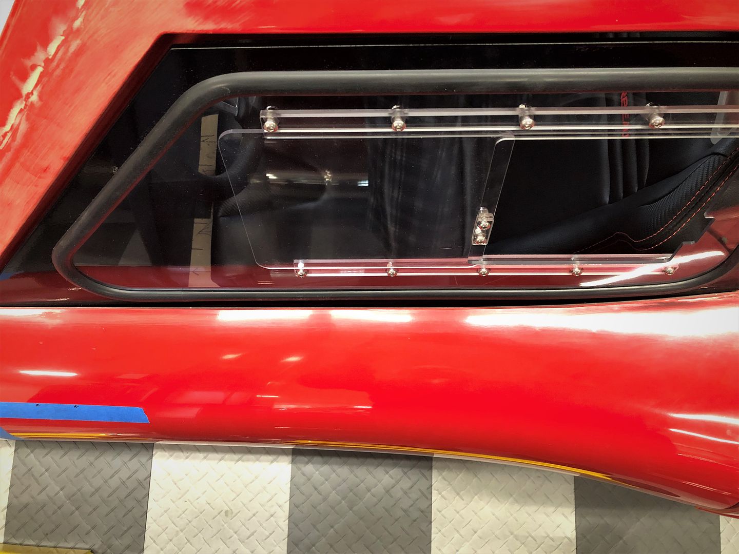
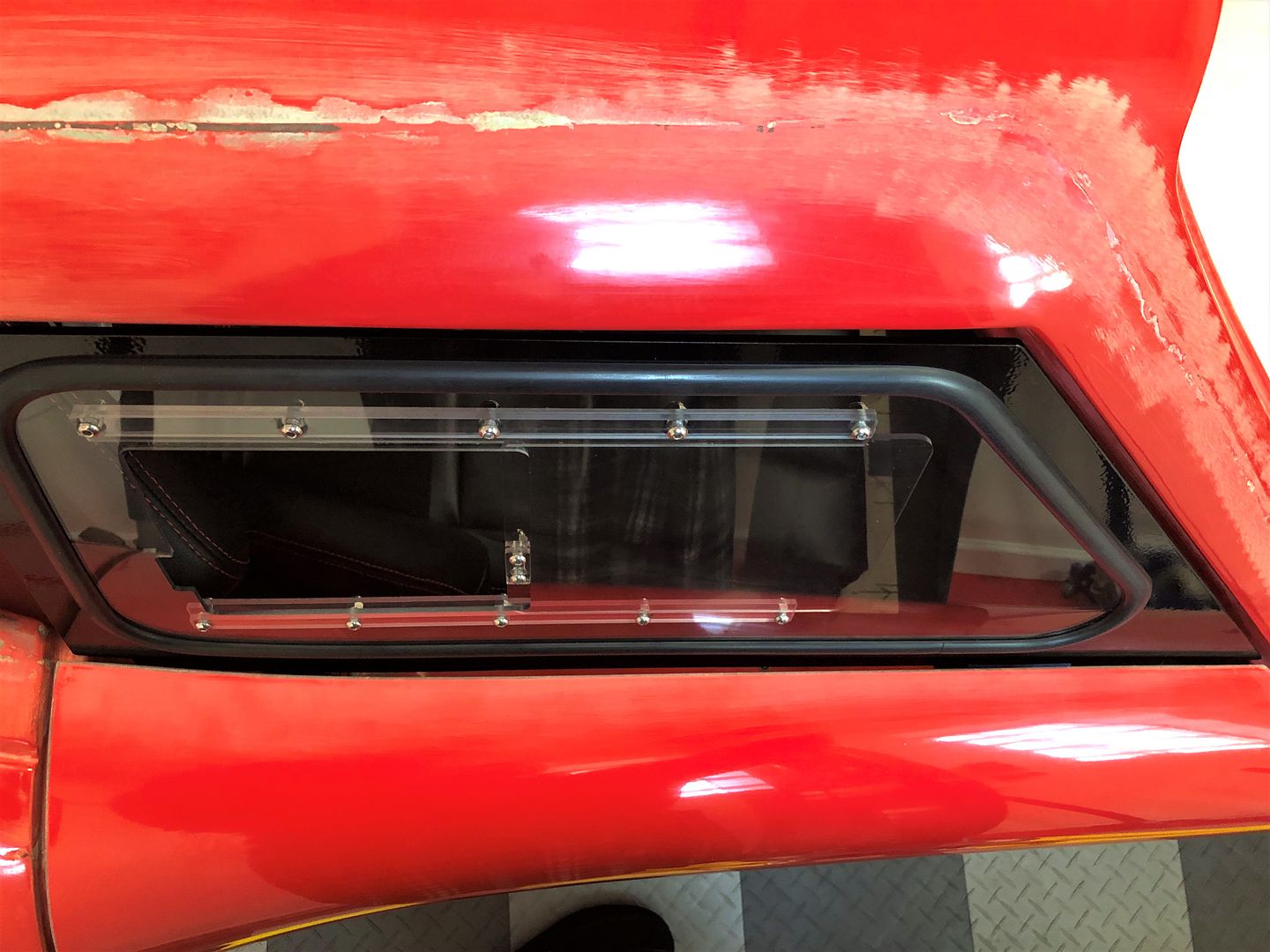
I ended up using 3M HSRF. I was able to adjust the windows and get the gaps slightly smaller than I pictured before. I decided the gaps were just too irregular to glue on fill pieces. Resin with filler, chopped glass, etc. potentially would be a little stronger. But I had the HSRF and am familiar with using it. Plus, I do expect the windows will stay on most of the time. So the edge will usually be protected. Not that I think the result is fragile. It isn’t at all. This is the process I used. First sanded a 1/8-inch plus bevel with 80 grit paper on the top of the doors through the gel goat. Plus roughed up the remaining edges plus about 1/2-inch back on the gel coat along the top. Then used clear packing tape to wrap all the parts of the windows that would be in contact with the HSRF, and gave them several coats of car wax so they would release. Then with the windows in place, put wood strip fillers along the bottom edges with double back tape to dam the HSRF when pushed into place. The wood strips had the same clear packing tape and wax treatment.

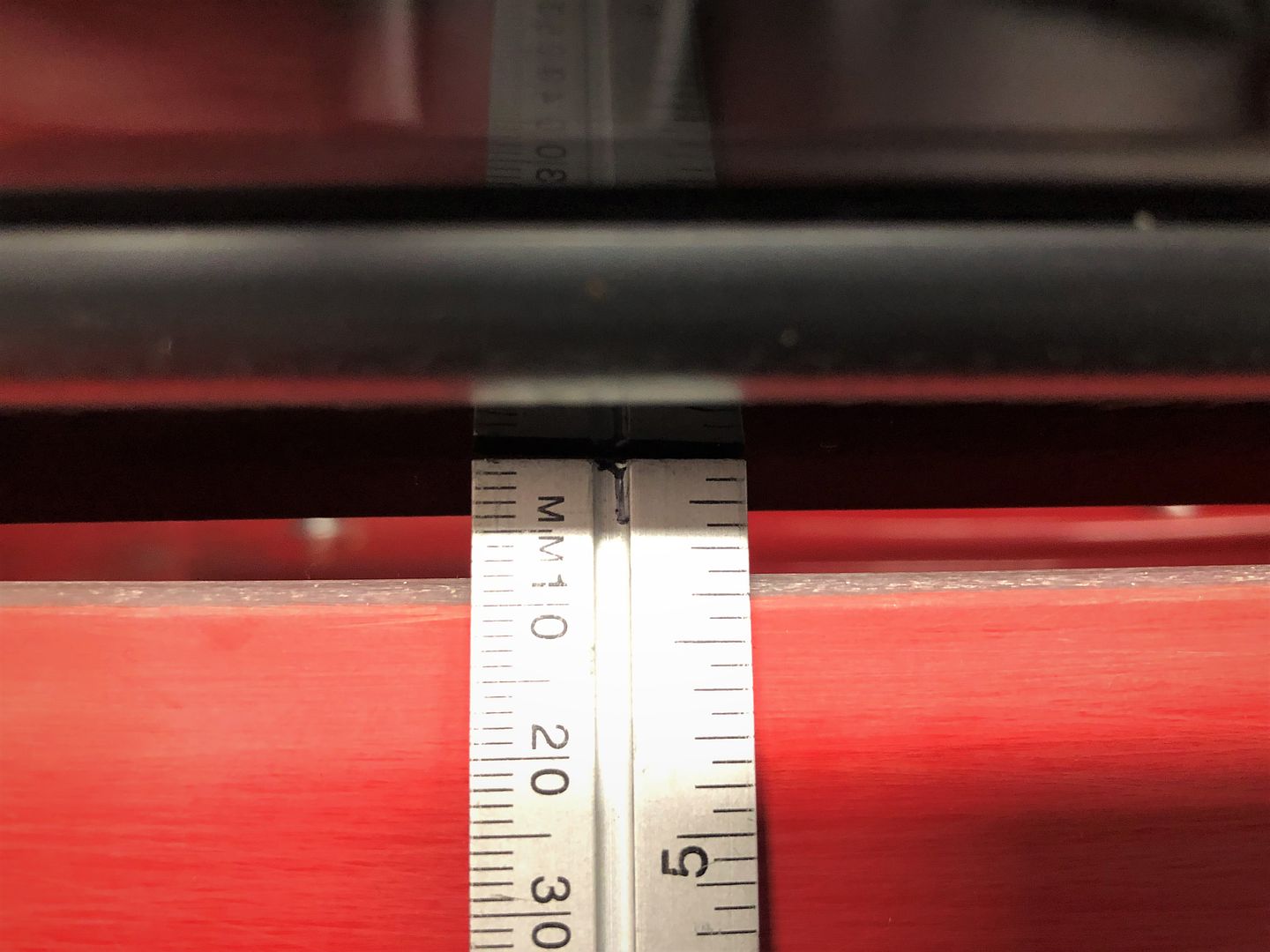
With everything in place, filled the gaps with HSRF. Did it in two applications. First pushed firmly in to make sure everything was filled. Second to get as straight and even with the top of the door contours as possible. HSRF is not easy to sand if you haven’t heard that before. :p After a couple hours, popped the windows off and they released relatively easily. Removed the door shells and finished them on the workbench in the basement. There were a couple places to fill and touch up, but generally turned out well. Sanded the top and bottom flush with the doors. There’s a very slight ridge along the top edges. HSRF just doesn’t feather out like Rage Gold or whatever, plus is hard as a rock. But it’s straight and even, and one pass with body filler during paint should blend it completely. This morning put everything back together and it’s a huge improvement. I’ll add a thin piece of self-adhesive gasket or whatever at final assembly and should be good. Couple pictures of the finished product. The pictures are a little shadowy. The final gap is about 1/32-inch plus, and most importantly even all the way across.

Image

Image

I also finished mounting the Peter Brock sourced side mirrors I showed earlier. He provides detailed instructions including the recommended locations. They’re for a Superformance Coupe, but the locations seem to be fine here as well. He provides a backing plate and locknuts. But I decided I wanted the backing plate and nuts to be permanently captured so I didn’t have to reach inside the doors to mount and remove the mirrors. Especially since I’m planning door cards that will close the openings in the doors, and also because the mirrors are pretty wide and I may have to remove if/when using my existing trailer. So I made new backing plates out of 16 gauge steel and captured some flanged nuts with a second piece of aluminum and a 6-32 bolt. No pictures, but a simple fabrication and now bonded in place at the two mirror locations inside the doors. Mirrors are very solid, and easy to take on/off from the outside only with a ball end hex driver.

Image

Image

Two more items off the list! Doesn’t get old seeing this sitting in my garage.

Image

Tomorrow we have a club event that should be pretty amazing. I’ll find out how much I can talk about it after it’s over. Kinda sorta a track day unlike anything I’ve done with the Roadster. Stay tuned.
 
Discussion starter · #275 ·
You may have to increase the gap to 3/32-1/8 or so. Primer and paint will take up a lot of the gap. Talk to your painter.
All good and considered that. The way the window is mounted any added thickness would just move the window into the opening slightly, and is easily accommodated by the adjustable mounts and the bulb seal around the body.
 
Discussion starter · #277 ·
My error, I was referring to the gaps above and in front of the window frame, between the w-frame and body. I thought those were in play, not just the door to window gap. Also, the door/window will move around a little with bumps. BTW, what happened to the door gap?
There will be bulb seal all around the door opening that the windows close against. Those gaps are fine and will within the range of the bulb seal. My experience with these cars is the frame and body are both very stiff and in fact doesn't move around at all. But if it did, the bulb seal would handle it. Everything about the window fit is exactly how it's intended to be and will be fine.

Regarding the door gap, I assume you're suggesting the gap is too wide. It does look wider than it actually is because of the picture angle and the gel coat being removed by the slight radius on both sides. But the gap is wider than I planned. I typically shoot for 3/16-inch unfinished, which it is everywhere else. The front of the doors are 1/4-inch. I talked about this previously in the build thread. I set the gaps before fitting the front cowl, which in hindsight was a mistake and I recommended to other builders do the cowl first. When I installed the cowl, and pulled it down for the best alignment along the body, the gaps on the doors opened up slightly. Finishing will close it up some, and will have cushioning material behind.
 
Discussion starter · #278 · (Edited)
Gen 3 Coyote Engine Cover

Another one of my to-do items was to address the Gen 3 Coyote engine cover. Dressing up the Coyote is not an easy task, and Ford made the Gen 3 even more difficult with the added plumbing for the Direct Injection (DI) system. With the additions, they gave up on coil covers and extended the intake manifold cover to hover over the heads. For the Mustang, this meant fitting them around the shock towers and other underhood components. So made for a “different” look to say the least.

Image

Mocked up in the Gen 3 Coupe, didn’t look too great either. Plus is too wide for the chassis and too high for the cowl.

Image

Needless to say, something is needed to cover some of this up.

Image

First thing I did was whack off the oddly shaped extensions or wings as they’re affectionally called.

Image

Reasonable start, but decided I wanted some type of extensions that would cover more up but look like they belonged. And fit in the available space. Factory Five put a Gen 3 Coyote in a 33 Hot Rod. Has an aftermarket intake, but they fabricated some extensions that went over the heads a bit, and that was an additional inspiration. Even though mine didn’t turn out anything like theirs.

First thing I did was make some mockups out of cardboard. Played with different shapes, widths, etc. I ended up with them about 4-1/2 inches wide and shaped to sort of follow the lines of the existing intake cover. Wider would have covered up more. But just looked out of proportion to me. Plus started covering things up like the oil filler and dipstick. Then decided needed to do something to dress up the extensions. Considered routing some slots, like Factory Five did, but didn’t care for that look. Plus exposed what I was trying to cover up. Played around with a bead roller borrowed from a build buddy. Haven’t ever used anything like that. Had a little trouble getting straight lines. But in the end didn’t matter. It distorted the aluminum I wanted to use way too much. Plus it was kind of an old school hot rod look that didn’t really fit with the theme of the car or the more modern angular existing cover. What I finalized on was some 1/4-strips glued and riveted to the covers. Sort of matching some similar lines on the existing cover and had a look I was happy with. I don’t pretend to be a designer or particularly artistic, so this was the best I could come up with. Also considering what tools and capabilities I have. I am happy with the result though. Even though as usual it was more work and took longer than I expected.

What I did was trim the existing plastic cover down to where it was straight and had a 1/4-inch wide flat on the underside. Then made filler pieces from 1-inch wide by 1/4-inch thick aluminum. Bonded these to the underside of the cover with JB Weld plastic bonder, available at HD. Probably there is something out there more exotic that is stronger. But I drilled and tapped for some 4-40 flat head screws that add some additional mechanical strength. It’s sitting against a rib on the underside that has a filet of bonder against it. Bottom line, there isn’t a lot of stress and I don’t think it’s going anywhere. Then I made the extensions out of .040 aluminum, held onto the bottom of the 1/4-inch strip with a row of 4-40 screws. Then added the 1/4-inch strips on the top. Used JB Weld to stick down and hold. Then added 1/16-inch flat head rivets.

With the cover in place, found it was unstable in the front. The four balls that plug into grommets in the intake are toward the back of the cover and didn’t provide much support at the front. Ford also obviously saw this, because the Gen 3 cover has two added mounting points on the heads at the front. I made some brackets out of 16-gauge steel that matched up with those and attached to the bottom of the extensions. It’s a little bit of a dexterity test to reach under the extensions and start the nuts. But not something I expect to do too often and gives just the right amount of stability.

Enough talk. Here’s the final product. Just bare metal now. Will paint the body color when the car is painted along with the darker color plastic on the existing cover. The lighter color will stay the way it is. Hard to get a good angle with the cowl in the way, plus it’s a little bright in the shop with the sun shining. But I’ll take that after all the rain we’ve had. First picture from the bottom showing how it's put together. Then the finished side with it installed.

Image

Image

Image

That’s it for a few days. Tomorrow prep for London including installing the new windshield in my Roadster. Assuming FedEx delivers on time. Yep, joined the broken windshield club while sitting in the garage last Monday/Tuesday. Hope to catch up with some of you in London. Looking forward to it as always.
 
261 - 280 of 379 Posts