Factory Five Racing Forum banner

Indy14 Build Thread

102K views 94 replies 30 participants last post by  JKleiner 
#1 ·
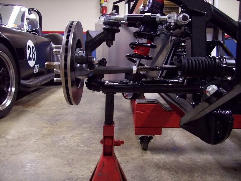
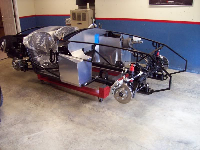
Well, I guess its time to start my build thread. I'm Steve from Indiana and my Factory Five Mk 4 Roadster has arrived and is being built. I've waited 43 years for this type of car. I was lucky enough to meet a gentleman named Jeff that let me ride in his Factory Five Roadster and will help me build my car. I will create a website for my build because looking at others was the way I learned most of what I know about Factory Five Roadsters. Also just to be correct, Jeff will build the car. I may be able to hand him a tool or part when needed.
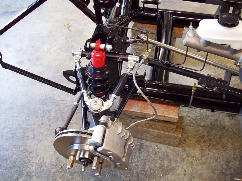
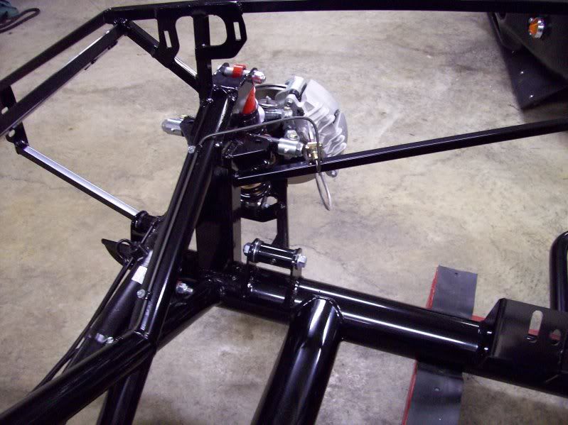
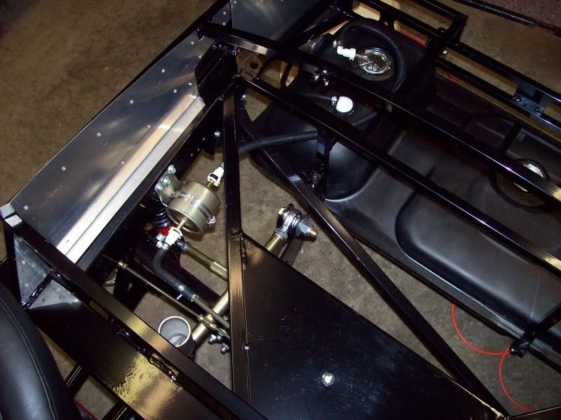
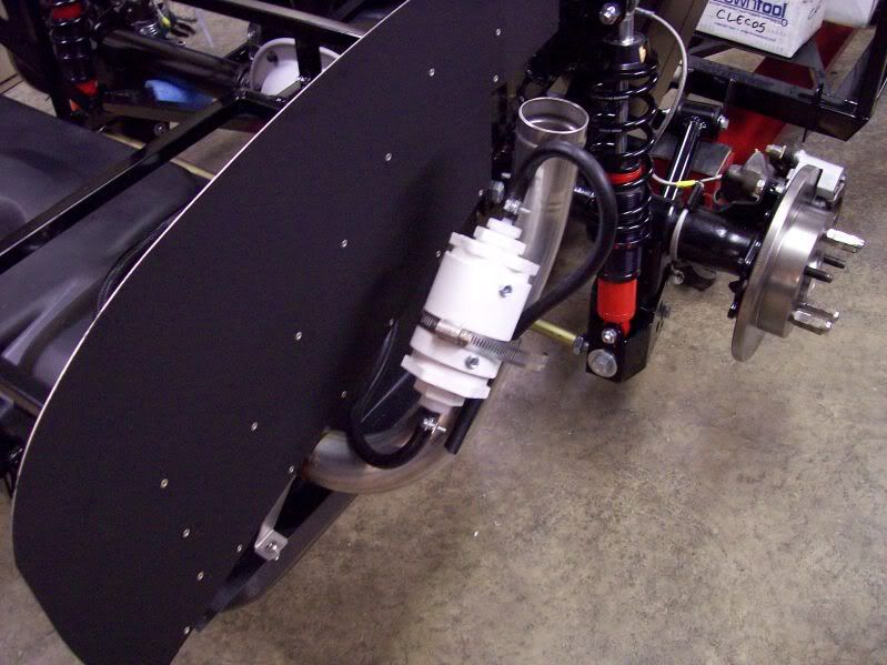
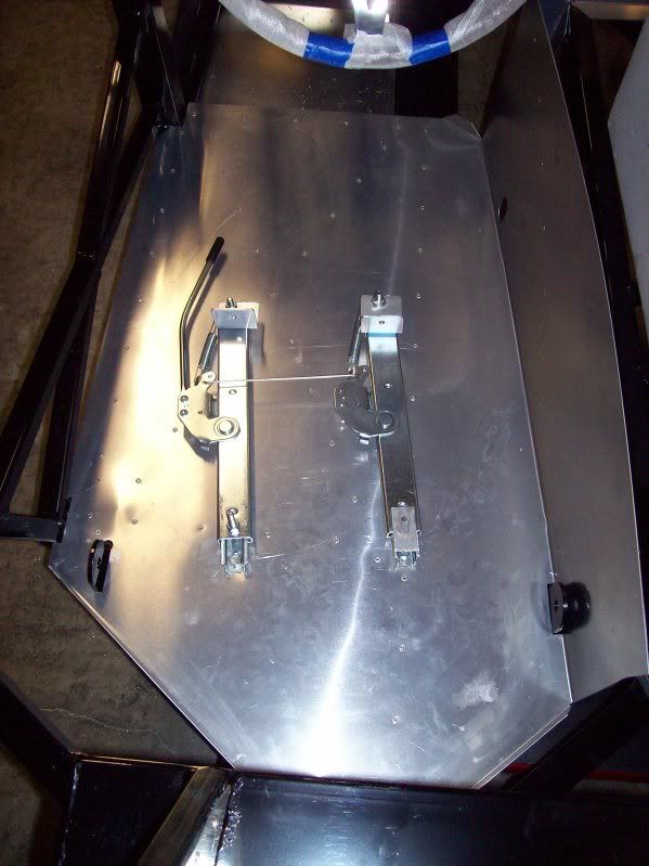
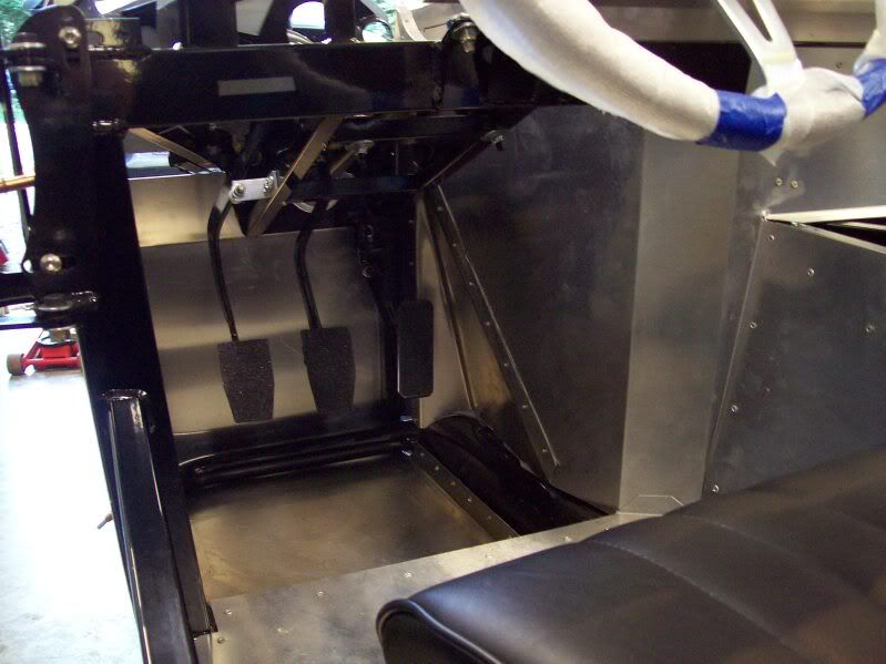
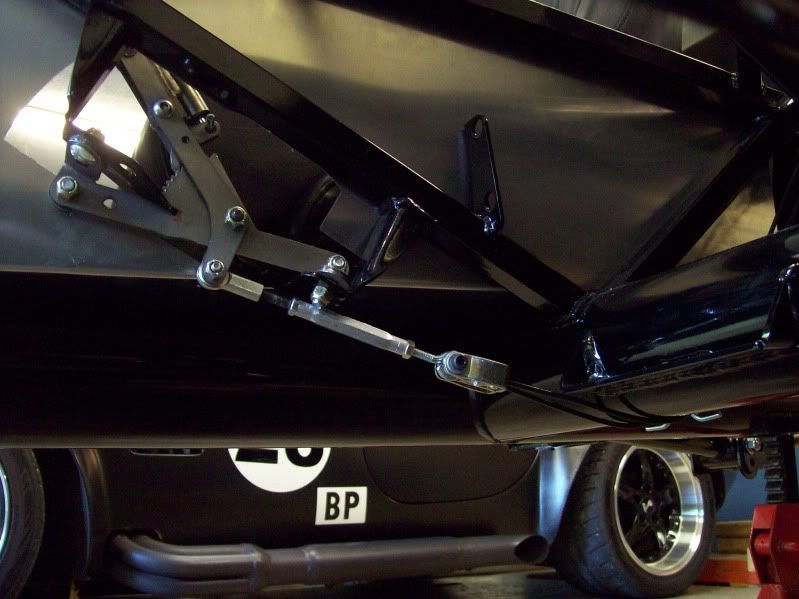
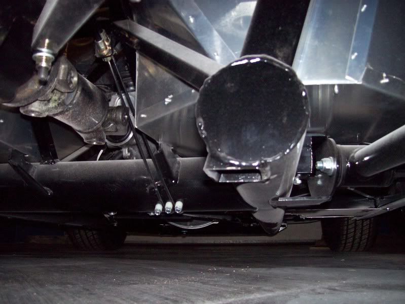
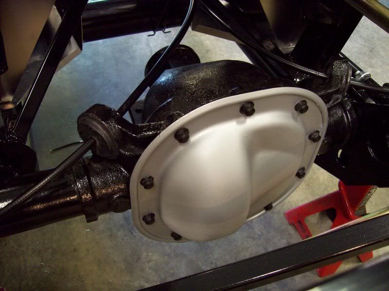
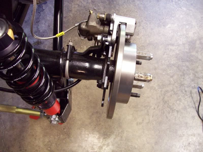
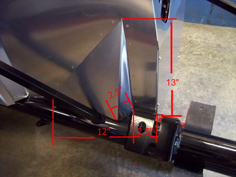
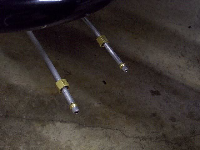
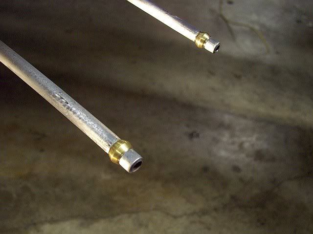
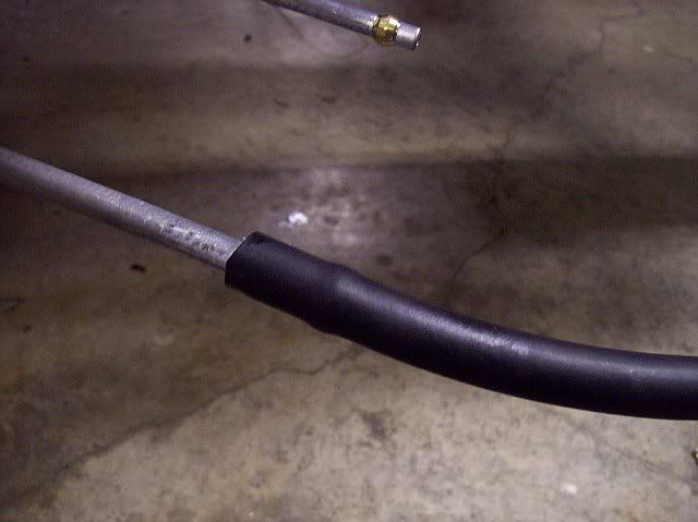
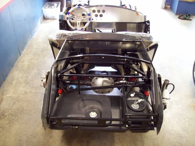
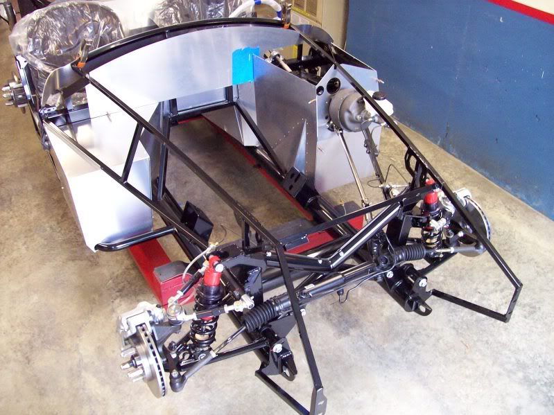
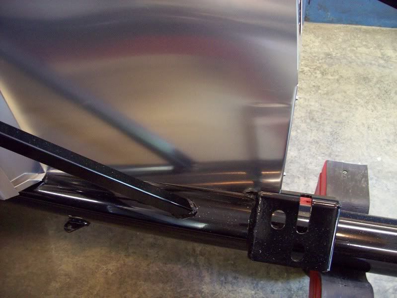
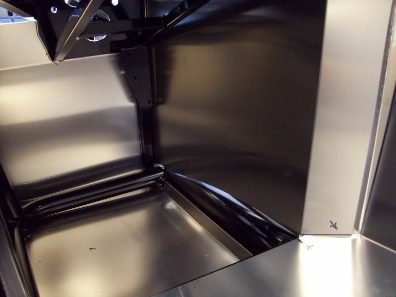
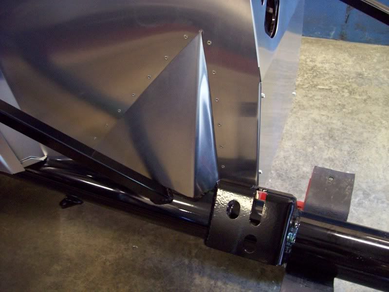
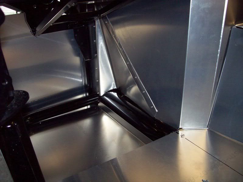
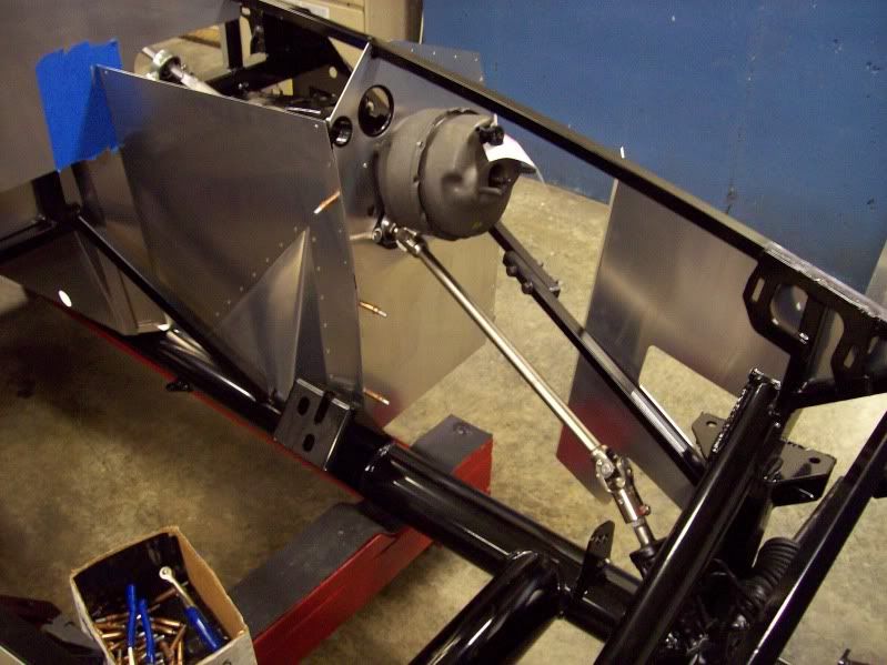
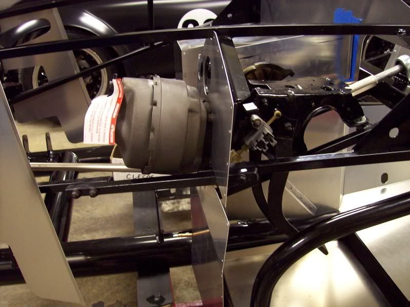
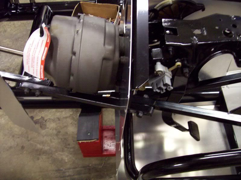
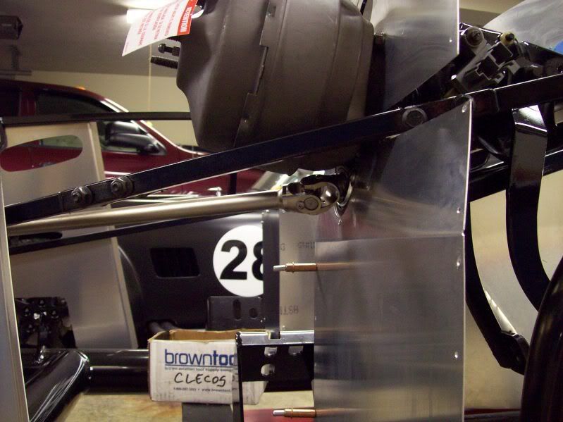
What prompted me to start a build thread was after I went out to help Jeff work on my car. He had installed the brake & fuel lines. He did an excellent job. Looks like it came from a factory.
Thanks for doing a great job.
See the website for progress.
 
#2 ·
Looks great Steve, I know you made the right choice with FFR and Jeff is doing a wonderful job so far. You are going to like the power steering and brakes. Keep us updated.

Mike
 
#3 ·
Well thanks for the kind words Steve!

I always enjoy the build threads and have been meaning to get one started for your car. This thread should motivate me to actually do it! I made a post last month with some early progress reports HERE then had a family emergency as well as some other obligations crop up and didn't keep the updates coming. I have a ton of pictures on my computer at home that need to be uploaded to photobucket so I can post them. Promise---I'll do it in the next couple of days then back up and add them to this post chronologically. Between Steve's website & photos and mine we should be able to document the build of #7276 pretty well.

Until then here a few teasers. First as Steve's car arrived and met it's older sibling #5946:


Here are some from the weekend before last:


Guess I better head home and get busy uploading pics!

Cheers,
Jeff
 
#55 ·


Cheers,
Jeff
This thread is great - I am enjoying watching the progress.

Just to back up a little, can I ask about the small chassis trolley you have in this pic? I think I should make one while waiting for my kit to arrive. Got any dims you could share? Even a space between the main chassis rails and the overall length would do. I could measure mine when it arrives I know, but for now it's on a boat somewhere and this would let me get a little job out of the way!

Thanks heaps
 
#4 ·
the build looks great guys!

what is the finish that you applied to the rear alum panels? did you just powdercoat the outside or is it something else....?
 
#7 ·
In addition to the revised shape of the Mk4 some of the changes are rolled cockpit & wheelwell edges, hidden body mounts and new trunk hinges. The trunk hinges are similar to the Breeze/"Convincor" units many of us have used and offer a wide range of adjustability:


Cockpit edges are now rolled from the factory. They will still require attention, particularly at the doors, but are much closer to finished than the previous bodies:


The wheelwell roll is a HUGE improvement over the ragged finish of earlier cars:


Finally a look at what I think is my favorite change---no more Frankenstein bolts for the side body mounts! (I didn't realize my helper was in the shot till after I had taken it!)


This will be so much nicer than dealing with the old method of shims, bolts and contrary speed nuts. I think I'll just cut some slots into the underside of the rocker panel then drill and tap the outer 2X2 rail. Slots will allow the body to be moved in or out to optimize fit at the doors; when it's right simply tighten the bolts and call it done!

That's all for the first look. After these photos were taken Steve and his son Sean came over and we removed the body. I'll add more tomorrow detailing the beginning of chassis assembly.

Oh, BTW,
what is the finish that you applied to the rear alum panels?
3M ruberized undercoating. Rough the aluminum up good with 80 grit to give it some tooth then apply two or three coats.

Cheers,
Jeff
 
#6 ·
OK, got some photos loaded so lets go back to the beginning and first impressions.

Steve's car, #7276, was delivered to my house by Dennis and Jo, the same Stewart Transport team that delivered mine. Quite a contrast though with a temperature delta of greater than 100 degrees! Mine arrived the day after the Indianapolis Colts won the Superbowl, which was the coldest day of the year with a HIGH temperature for the day of -10. This time the temp was well above 90! Lots more boxes this time too. Steve opted for the complete kit:


Over the next few evenings I did inventory and got a look at the latest parts. First and most visible is the new Mk4 body of course. I'll admit to being skeptical when it was introduced but have to say that it truly does have some nice improvements. The parting lines are the first thing that most people look at. Personally I don't care how big the boogers are as long as they don't have voids and the panels align. Earlier bodies were hit and miss but if this sample of one is any indication they've improved this area:


No voids and alignment is spot on. As the reflection in the photo below illustrates the major body is pretty straight and slick, moreso than some of the earlier ones I've seen which had a lot of waves.


More in the next post.

Jeff
 
#8 ·
About a week after the car arrived Steve and his son Sean came by and we lifted the body off. I marked panels then started in with the first mod. Like many other Mk3 owners I made an extension to the left side of the driver's footbox in addition to doing the well documented dv/dt "Rod Mod" on the right side. With the Mk4 FFR took care of the left side by pushing it out as far as possible. The right side still leaves some wasted space when using a pushrod motor. Rather than bending the entire panel, which would have effectively made it shorter horizontally affecting it's fit at the tunnel horseshoe, I cut a triangle out of it and bent up "pyramid" to provide some extra room around the throttle pedal.

Before, with the flat panel:


And after:


I think it's well worth the effort. My Mk3 with kickouts to both sides measures 16" wide across the pedal area. After the mod this one is 18"!

Jeff
 
#9 ·
Here's the plan for Steve's car: #7276 is a Mk4 3 link complete kit. A couple of breaks from the complete kit recipe will be the addition of power brakes using a Fox pedal box and power steering. Engine will be a carbed Ford Racing 340HP X302 coupled to a new T5-Z. Rear end will have 3.55 gears. Steve is going for a traditional look with low back roadster seats, chrome bar, and classic guages all riding on a set of those great looking chunky sidewall 15" tires with Halibrands! I'll let him reveal his color scheme when he's ready!

Next order of business after the footbox was to install the power rack, steering shaft and pedal box, then make the frame mods necessary to accomodate the brake booster. Sorry, I failed to get a pic of the enlarged hole in the footbox front bulkhead. I used a 3 1/4" hole saw 'cause it was handy but 3" will do.

Photo below shows the rack installed along with the steering shaft. Fox body pedal box is in along with the booster. A Fox booster must be used; SN 95 units are larger diameter and will interfere with the steering shaft. You can see where the 3/4" tube was removed and replaced to the right of the booster. I did a similar mod when I built my car and on both used plugs of 5/8" key stock in the tubes so that the bolts clamp the tubing rather than crush it.


Here is another view.


Look at this shot below and you'll see that I used flanged bolts to space the booster away from the bulkhead about 3/8". The Mustang firewall is double wall sheetmetal with a spacer between the two layers. You must use a spacer of some sort when doing this mod to keep the pedal, pushrod and booster in the same relationship. Without it the pedal will come into contact with one of the tubes under the steering shaft in the pedal box. If you look closely you'll see that a piece of memory foam seals the opening between booster and bulkhead.


Finally a look below the booster. To provide clearance the flanged bearing must be installed inside the footbox with the collar and setscrews pointing rearward.


Since Steve will have rear discs we'll be using a SN95 master cylinder with 1.0" bore. The critical dimensions where it meets the booster are identical to the Fox body disc/drum master cylinder.

Coming next---rear axle rebuild and prep...

Jeff
 
#10 ·
Since the complete kit no longer includes a rear axle we began a search for a suitable unit before the car arrived, locating one for a good price about 45 minutes from home. It is an 8.8 from an unknown vintage '94-'98 Mustang GT. In the end not much more than the housing and carrier will remain as it left the factory. Not much to look at (I pulled the cover and let it drain outside for a couple of days to keep that lovely friction modifier smell out of the shop :puke:


It got better though. Ready to install now with 3.55 gears, rebuilt trac-lock, Richard Oben/ North Racecars caliper brackets and Fox width axles. The FFR LCA brackets and "banana" are on as well as new calipers & rotors. Re: the banana bracket---it appears that after all these years they still haven't realized that the bolt they are shipping for that forward leg is too short! I did the caliper swap, mounting them to the front rather than the rear. Some have reported interference with the coilover when on the rear; it didn't look to be a problem to me but a nice benefit to the front mount is the ease of parking brake cable routing. Rear mount requires an "S" while the front mounting only needs a gentle "U". I cut off the no longer needed quad shock mounts and ground the welds smooth to allow the factory anti-moan braces to be used (they have to swap with the calipers as well).


Thanks to the Mk4 bolt in panhard bar mount installing the rear is much easier than on earlier cars that required some wrestling to get it through the tubing. One of two items missing after inventory was the LCA to chassis mounting hardware. I put in place with some temporary bolts then changed over to the permanent fasteners when they arrived.


Next up is moving to the front to go as far as possible while waiting for he backordered lower control arms to be delivered...

Jeff
 
#11 ·
While awaiting the front lower control arms I began assembling the rest of the front end. We've heard the occasional reports of the upper ball joint backing out of the UCA. Some guys give them a tack weld to lock them in. On my car they were super tight threading in but I used still used Locktite. They haven't budged and I don't think they will. With Steve's car the joints threaded in by hand. I gave them a dose of Locktite and torqued them tight. For some extra assurace I drilled thru the UCA into the joint and added a 1/8" spring pin to mechanically lock it in place. If the joint should ever need to be removed the pin can be pulled out. No worries about interference internally; it is well above the ball:


The LCAs eventually arrived so I assembled the rest of the suspension. I can't stand to see the front pointing all wonky so the springs were set for an approximate 4.5" ride height and I put my guages on to loosely adjust caster, camber and toe:


With the new FFR spindles and UCA mounting points the geometry looks pretty good:


Brakes were installed and lines were run:


At this point I was ready to put a "done" stamp on the suspension... then the news broke about some failures of the bolts that secure the steering arm to the spindle. It will have to get partially torn down again to replace those, so this was a practice run!

Jeff
 
#12 ·
Brake lines are one of those things that truly are "builder's choice" with no two being identical. For the front I crossed on top of the "X" member. The rear line comes forward, down the 2" X 3" then along the 4" round tube to the back:


Installed the gas tank so that I could work the fuel line in at the same time. The car will use a mechanical pump so no return is needed. It crosses at the rear after the filter then comes up the outside of the 4" round tube along side the rear brake line:


To complete the tank/line installation I made up a home brewed charcoal canister for the vent using a combination of PVC pipe, barbed fittings and activated charcoal intended for aquariums. I made one like it when I did my car and it works well to assure that there is no gas odor; believe me, if there was my wife would let me know about it!


Steve was here and helped me put it together. He was totally intrigued and asked where I got the idea---I told him it was our genius forum brothers who came up with it, not me. Thanks guys!

Next we start getting Steve fitted to his car...

Jeff
 
#13 ·
Last Saturday Steve came over so we could start getting the car set up for him (my wife teased him that it was like going for a prom dress fitting). Earlier he had decided to add an adjustable seat track for his low back driver's seat. The slider needs to be parallel to the tunnel so that the seat remains equidistant from it when moved for and aft. If the track is set in straight ahead the seat will collide with the tunnel when moved forward. The challenge is getting it in a position where it can mount to the steel plate under the floor or chassis tubes, and not just floor aluminum. After some swearing and 're-engineering" a workable location was found and it was bolted it in:


Steve was most comfortable with the seat turned just a bit to be parallel with the steering wheel. I made some simple brackets to attach the seat to the adjuster. Here is the seat all the way back:


And all the way forward:


Notice how it is the same distance from the tunnel in both positions.
The passenger seat is fixed, set at the same angle and mounted on 1" square aluminum tubing to match the driver's seat height.

With the seat location set we determined pedal placement. The gas pedal is the one provided with the complete kit. The pedal pad is spring loaded and kind of funky---without a foot on it the thing springs toward the driver with it's top out farther than the bottom. I redrilled the pivot point and ground a flat on the arm to make lay back. Odd...??? With that in place we made note of how much adjustment was needed for the brake and clutch, removed them and made bends using my vise and big pipe wrench. After getting them where we wanted I made some pedal pads and covered them with the same black anti-skid material as the gas pedal. With the Mk4's newly designed and expanded LH footbox panel and the added kickout to the right there is a good bit of room:


When Steve came for his "fitting" he brought the backordered parking brake lever so that will be the next order of business...

Jeff
 
#67 ·
Last Saturday Steve came over so we could start getting the car set up for him (my wife teased him that it was like going for a prom dress fitting). Earlier he had decided to add an adjustable seat track for his low back driver's seat. The slider needs to be parallel to the tunnel so that the seat remains equidistant from it when moved for and aft. If the track is set in straight ahead the seat will collide with the tunnel when moved forward. The challenge is getting it in a position where it can mount to the steel plate under the floor or chassis tubes, and not just floor aluminum. After some swearing and 're-engineering" a workable location was found and it was bolted it in:


Steve was most comfortable with the seat turned just a bit to be parallel with the steering wheel. I made some simple brackets to attach the seat to the adjuster. Here is the seat all the way back:


Notice how it is the same distance from the tunnel in both positions.
The passenger seat is fixed, set at the same angle and mounted on 1" square aluminum tubing to match the driver's seat height.


Jeff
Hi Jeff,
Is there any concern about clearance issues with the body when the seats are mounted before the body is on? I'm using Cobra Clubmans, and I'd like to do the mounting now (pre-body) but afraid I might have contact with the higher backs and insides of the cockpit.
Or am I safe keeping it centered between side & tunnel?
Thanks
 
#14 ·
Thanks

Wow. I love your posts. Even though I have been there when "we" work on the car, it great to see your pictures and explanations.
Thanks for doing such a great build.
 
#15 · (Edited)
While awaiting the back ordered e-brake lever Steve debated whether to go with tunnel top or side mount. When it arrived it was decision time---he chose side mount. Based on the manual and backorder list I was expecting a spring tensioned OEM Ford lever with the "T" cable. Nope, not even close. The FFR instructions included with the unassembled lever have a revision date of 7/21/10 so I think they have recently gone to an in-house design that works differently. It required some rework of cables and the lever linkage but will work fine.

The hole in the tunnel aluminum had to be opened up and reshaped for clearance:


As delivered the lever does not provide a means to adjust slack out of the cables without disassembling the linkage to thread in or out the male & female rod ends. I picked up a hardware store turnbuckle and installed it between the two:


The manual states that you can use cables for the year of the rear end...True, but not straight from the box! This lever wants to pull the cables from under the 4" cross tube, with the sheath attached a few inches above. The inner cable is only 6-7" longer than the outer sheath---not enough. I cut the end off of the inner and pulled it out. Mocked up the sheath from the wheels to the anchor point and determined that they needed to be shortened by ~20". Pulled the end off, cut the sheath, reinstalled the end and fed the cables back thru. With that done I could now route the cables and determine where to swedge on new ends to meet the links at the turnbuckle. Like so much with these cars you sometimes have to make it up as you go! Here is a look at the cables crossing under the 4" cross tube. I screwed 1/4" long tubular nylon spacers to the crossmember to keep them separated:


Continued>>>
 
#16 · (Edited)
Like I did with my own car, to secure the cables I routed them through the unused upper 4 link ears on the rear axle. I found tapered rubber stoppers of the proper diameter, drilled a hole in the center for the cables to pass through and used black silicone to hold 'em in place:


As mentioned earlier, the e-brake cables make a nice sweeping "U" turn when the calipers are mounted ahead of the axle:


Steve talked with Patti at FFR last week checking status of his backordered 15" Halibrand replicas---looks like another 2-3 weeks. As soon as they arrive #7276 will become a roller! While waiting it's time to start stringing wires...

Jeff
 
#17 ·
Exciting News

Just ordered the Ford M-6007 x302 engine.
Can't wait to get that.:001_tt1:
 
#20 ·
Just ordered the Ford M-6007 x302 engine.
Can't wait to get that.:001_tt1:
There were 200 on B/O when I ordered mine. Somehow It arrived almost exactly the day they targeted which was about 5 weeks. They have been in high demand since they were released.
 
#25 ·
Rob,
Here in Indiana before we can get a VIN and register we only need to have a police officer sign off on two seperate documents. The first is verifying that major components such as engine, trans. and rear end don't have "hot" numbers. The second one is to confirm that the state issued VIN is affixed to the vehicle.

No safety inspections; personally I have mixed feelings on that. On one hand it makes it easy. The flip side though is that there isn't any safeguard to keep someone from putting a poorly constructed bucket of $h!t on the road.

Jeff
 
#29 ·
Mick,
Below is a cut & paste of my post answering that question some years ago when I built my car. Difference being mine is EFI while this one is using a mechanical pump, so the line at the rear will be under suction rather than pressure.

Here is my method for mating hard to soft fuel lines.

Rather than making half a flare per FFR's recommendation I used 5/16" and 1/4" compression fittings to create some homemade "barbs" on the steel lines.

Install and tighten a compression fitting as if you were going to use it conventionally, then remove the coupling. What we're doing is swedging the ferrule onto the steel line:


Next cut the compression nut off of the hard line (I used a Dremel with a cut off wheel):


Now push the EFI rated hose well past the ferrule. It takes some effort (a touch of white lube helps) but we want that resistance between hard and soft lines:


Finally install the clamp:


As you can see, with the clamp in place and tight it becomes nearly impossible for the hose to move over the larger diameter created by the ferrule swedged onto the hard line.
After posting the photos of how I routed the line in Steve's car I uncovered some information revealing that a mechanical diaphram fuel pump would rather push through a filter rather than pull through so I removed the one at the rear and revised the lines. I'll add one in line between the pump and carb.

Hey Al!,
While building my car I took lots of photos but didn't post much. As I said above, I always enjoy seeing other's builds come together and wanted to do a better job of documenting this one. Hopefully some of my pics and comments will be useful, or at least fun to see! Old dogs like you and me remember some of the very first FFR builds to be chronicled via the internet on the original Cobraforum; guys like Avi, Wade C. and Wade L., Dino's infamous 2 day build... We've come a long way, eh?

Cheers,
Jeff
 
This is an older thread, you may not receive a response, and could be reviving an old thread. Please consider creating a new thread.
Top